
User Manual


Table Of Contents
- 24-Port Gigabit Smart Managed Pro Switch with PoE+ and 2 SFP Ports Model GS724TPv2
- Contents
- 1. Get Started
- Switch Management Interface Overview
- Change the Default IP Address of the Switch
- Discover a Switch in a Network With a DHCP Server
- Discover a Switch in a Network Without a DHCP Server
- Configure the Network Settings on Your Computer
- Access the Web Browser–Based Management Interface
- About the User Interfaces
- Use a Web Browser to Access the Switch and Log In
- Web Browser–Based Management Interface Device View
- Interface Naming Conventions
- Configure Interface Settings
- Context-Sensitive Help and Access to the Support WebSite
- Register Your Product
- 2. Configure System Information
- 3. Configure Switching
- Configure Port Settings
- Configure Link Aggregation Groups
- Configure VLANs
- Configure a Voice VLAN
- Configure Auto-VoIP
- Configure Spanning Tree Protocol
- Configure Multicast
- View the MFDB Table
- View the MFDB Statistics
- IGMP Snooping Overview
- Configure IGMP Snooping
- Configure IGMP Snooping for Interfaces
- View the IGMP Snooping Table
- Configure IGMP Snooping for VLANs
- Modify IGMP Snooping Settings for a VLAN
- IGMP Snooping Querier Overview
- Configure IGMP Snooping Querier
- Configure IGMP Snooping Querier for VLANs
- Display IGMP Snooping Querier for VLAN Status
- Configure a Static Multicast Group
- Remove a Static Multicast Group
- Configure Multicast Group Membership
- Configure the Multicast Forward All Option
- View and Configure the MAC Address Table
- 4. Configure Quality of Service
- 5. Manage Device Security
- Configure the Management Security Settings
- Configure Management Access
- Configure Port Authentication
- Configure Traffic Control
- Configure Access Control Lists
- Use the ACL Wizard to Create a Simple ACL
- Configure a MAC ACL
- Configure MAC ACL Rules
- Configure MAC Bindings
- View or Delete MAC ACL Bindings in the MAC Binding Table
- Configure an IP ACL
- Configure Rules for a Basic IP ACL
- Configure Rules for an Extended IP ACL
- Configure IP ACL Interface Bindings
- View or Delete IP ACL Bindings in the IP ACL Binding Table
- 6. Monitor the System
- 7. Maintenance
- A. Configuration Examples
- B. Specifications and Default Settings
Monitor the System
263
NETGEAR 24-Port Gigabit Smart Managed Pro Switch with PoE+ and 2 SFP Ports Model GS724TPv2
6. Select the check boxes that are associated with the physical ports for which you want to test
the cables.
7. Click the Apply button.
A cable test is performed on all selected ports. The cable test might take up to two
seconds to complete. If the port forms an active link with a device, the cable status is
always Normal. The test returns a cable length estimate if this feature is supported by the
PHY for the current link speed. Note that if the link is down and a cable is attached to a
10/100 Ethernet adapter then the cable status might be Open or Short because some
Ethernet adapters leave unused wire pairs unterminated or grounded.
The following table describes the nonconfigurable information on the page.
Configure and View Logs
The switch generates messages in response to events, faults, or errors occurring on the
platform as well as changes in configuration or other occurrences. These messages are
stored locally and can be forwarded to one or more centralized points of collection for
monitoring purposes or long-term archival storage. Local and remote configuration of the
logging capability includes filtering of messages logged or forwarded based on severity and
generating component.
Manage the Memory Logs
You can set the administrative status and behavior of logs in the system buffer. The memory
log stores messages in memory based upon the settings for message component and
severity. These log messages are cleared when the switch reboots.
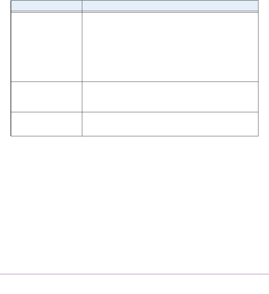
Table 56. Cable Test information
Field Description
Cable Status Displays the cable status:
• Normal. The cable is working correctly.
• Open. The cable is disconnected or a faulty connector exists.
• Short. An electrical short exists in the cable.
• Cable Test Failed. The cable status could not be determined. The
cable might in fact be working.
• Untested. The cable is not yet tested.
• Invalid cable type. The cable type is unsupported.
• No cable. The cable is not present.
Cable Length The estimated length of the cable in meters. The length is displayed as a
range between the shortest estimated length and the longest estimated
length. Unknown is displayed if the cable length could not be determined.
The cable length is displayed only if the cable status is Normal.
Failure Location The estimated distance in meters from the end of the cable to the failure
location. The failure location is displayed only if the cable status is Open or
Short.