
User Manual
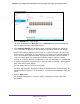
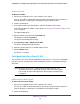
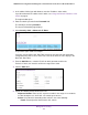


Table Of Contents
- 24-Port Gigabit Smart Managed Pro Switch with PoE+ and 2 SFP Ports Model GS724TPv2
- Contents
- 1. Get Started
- Switch Management Interface Overview
- Change the Default IP Address of the Switch
- Discover a Switch in a Network With a DHCP Server
- Discover a Switch in a Network Without a DHCP Server
- Configure the Network Settings on Your Computer
- Access the Web Browser–Based Management Interface
- About the User Interfaces
- Use a Web Browser to Access the Switch and Log In
- Web Browser–Based Management Interface Device View
- Interface Naming Conventions
- Configure Interface Settings
- Context-Sensitive Help and Access to the Support WebSite
- Register Your Product
- 2. Configure System Information
- 3. Configure Switching
- Configure Port Settings
- Configure Link Aggregation Groups
- Configure VLANs
- Configure a Voice VLAN
- Configure Auto-VoIP
- Configure Spanning Tree Protocol
- Configure Multicast
- View the MFDB Table
- View the MFDB Statistics
- IGMP Snooping Overview
- Configure IGMP Snooping
- Configure IGMP Snooping for Interfaces
- View the IGMP Snooping Table
- Configure IGMP Snooping for VLANs
- Modify IGMP Snooping Settings for a VLAN
- IGMP Snooping Querier Overview
- Configure IGMP Snooping Querier
- Configure IGMP Snooping Querier for VLANs
- Display IGMP Snooping Querier for VLAN Status
- Configure a Static Multicast Group
- Remove a Static Multicast Group
- Configure Multicast Group Membership
- Configure the Multicast Forward All Option
- View and Configure the MAC Address Table
- 4. Configure Quality of Service
- 5. Manage Device Security
- Configure the Management Security Settings
- Configure Management Access
- Configure Port Authentication
- Configure Traffic Control
- Configure Access Control Lists
- Use the ACL Wizard to Create a Simple ACL
- Configure a MAC ACL
- Configure MAC ACL Rules
- Configure MAC Bindings
- View or Delete MAC ACL Bindings in the MAC Binding Table
- Configure an IP ACL
- Configure Rules for a Basic IP ACL
- Configure Rules for an Extended IP ACL
- Configure IP ACL Interface Bindings
- View or Delete IP ACL Bindings in the IP ACL Binding Table
- 6. Monitor the System
- 7. Maintenance
- A. Configuration Examples
- B. Specifications and Default Settings

Manage Device Security
238
NETGEAR 24-Port Gigabit Smart Managed Pro Switch with PoE+ and 2 SFP Ports Model GS724TPv2
- Deny. Drop packets that meet the ACL criteria.
• Egress Queue. If the selection form the Action menu is Permit, you can specify the
hardware egress queue identifier that is used to handle all packets matching this IP
ACL rule. The range of queue IDs is 0 to 7.
• Logging. If the selection form the Action menu is Deny, you can enable logging for
the ACL by selecting the Enable radio button. (Logging is subject to resource
availability in the device.)
If the access list trap flag is also enabled, periodic traps are generated, indicating the
number of times this rule was evoked during the report interval. A fixed five-minute
report interval is used for the switch. A trap is not issued if the ACL rule hit count is
zero for the current interval.
• Match Every. From the Match Every menu, select whether all packets must match
the selected IP ACL rule:
- Enable. All packets must match the selected IP ACL rule and are either permitted
or denied.
- Disable. Not all packets need to match the selected IP ACL rule.
This field cannot be set if a mirror interface is already configured for the IP ACL rule.
• Src IP Address. Enter an IP address using dotted-decimal notation to be compared
to a packet’s source IP address as a match criterion for the selected IP ACL rule.
• Src IP Mask. Specify the IP mask in dotted-decimal notation to be used with the
source IP address value.
9. Click the Apply button.
The updated configuration is sent to the switch. Configuration changes take effect
immediately.
Modify the Match Criteria for a Basic IP ACL Rule
To modify the match criteria for a basic IP ACL rule:
1. Connect your computer to the same network as the switch.
You can use a WiFi or wired connection to connect your computer to the network, or
connect directly to a switch that is off-network using an Ethernet cable.
2. Launch a web browser.
3. In the address field of your web browser, enter the IP address of the switch.
If you do not know the IP address of the switch, see Change the Default IP Address of the
Switch on page 9.
The login window opens.
4. Enter the switch’s password in the Password field.
The default password is password.
The System Information page displays.