
User Manual
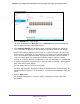
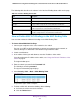
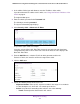


Table Of Contents
- 24-Port Gigabit Smart Managed Pro Switch with PoE+ and 2 SFP Ports Model GS724TPv2
- Contents
- 1. Get Started
- Switch Management Interface Overview
- Change the Default IP Address of the Switch
- Discover a Switch in a Network With a DHCP Server
- Discover a Switch in a Network Without a DHCP Server
- Configure the Network Settings on Your Computer
- Access the Web Browser–Based Management Interface
- About the User Interfaces
- Use a Web Browser to Access the Switch and Log In
- Web Browser–Based Management Interface Device View
- Interface Naming Conventions
- Configure Interface Settings
- Context-Sensitive Help and Access to the Support WebSite
- Register Your Product
- 2. Configure System Information
- 3. Configure Switching
- Configure Port Settings
- Configure Link Aggregation Groups
- Configure VLANs
- Configure a Voice VLAN
- Configure Auto-VoIP
- Configure Spanning Tree Protocol
- Configure Multicast
- View the MFDB Table
- View the MFDB Statistics
- IGMP Snooping Overview
- Configure IGMP Snooping
- Configure IGMP Snooping for Interfaces
- View the IGMP Snooping Table
- Configure IGMP Snooping for VLANs
- Modify IGMP Snooping Settings for a VLAN
- IGMP Snooping Querier Overview
- Configure IGMP Snooping Querier
- Configure IGMP Snooping Querier for VLANs
- Display IGMP Snooping Querier for VLAN Status
- Configure a Static Multicast Group
- Remove a Static Multicast Group
- Configure Multicast Group Membership
- Configure the Multicast Forward All Option
- View and Configure the MAC Address Table
- 4. Configure Quality of Service
- 5. Manage Device Security
- Configure the Management Security Settings
- Configure Management Access
- Configure Port Authentication
- Configure Traffic Control
- Configure Access Control Lists
- Use the ACL Wizard to Create a Simple ACL
- Configure a MAC ACL
- Configure MAC ACL Rules
- Configure MAC Bindings
- View or Delete MAC ACL Bindings in the MAC Binding Table
- Configure an IP ACL
- Configure Rules for a Basic IP ACL
- Configure Rules for an Extended IP ACL
- Configure IP ACL Interface Bindings
- View or Delete IP ACL Bindings in the IP ACL Binding Table
- 6. Monitor the System
- 7. Maintenance
- A. Configuration Examples
- B. Specifications and Default Settings

Manage Device Security
235
NETGEAR 24-Port Gigabit Smart Managed Pro Switch with PoE+ and 2 SFP Ports Model GS724TPv2
The System Information page displays.
5. Select Security > ACL > Advanced > IP ACL.
The previous figure shows an example.
The IP ACL page shows the current size of the ACL table compared to the maximum size
of the ACL table. The current size is equal to the number of configured IPv4 ACLs plus
the number of configured MAC ACLs. The maximum size is 100.
The Current Number of ACL field displays the current number of all ACLs configured on
the switch.
The Maximum ACL field displays the maximum number of IP ACLs that can be
configured on the switch.
6. In the IP ACL ID field, specify the ACL ID or IP ACL name, which depends on the IP ACL
type. The IP ACL ID is an integer in the following range:
• 1–99. Creates a basic IP ACL, which allows you to permit or deny traffic from a
source IP address.
• 100–199. Creates an extended IP ACL, which allows you to permit or deny specific
types of Layer 3 or Layer 4 traffic from a source IP address to a destination IP
address. This type of ACL provides more granularity and filtering capabilities than the
standard IP ACL.
• IP ACL Name. Create an IPv4 ACL name string that is up to 31 alphanumeric
characters in length. The name must start with an alphabetic character.
Each configured ACL displays the following information:
• Rules. The number of rules currently configured for the IP ACL.
• Type. Identifies the ACL as a basic IP ACL (with ID from 1 to 99), extended IP ACL
(with ID from 100 to 199), or a named IP ACL.
7. Click the Add button.
The IP ACL is added to the switch configuration.