
User Manual
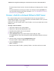
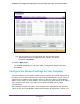


Table Of Contents
- 24-Port Gigabit Smart Managed Pro Switch with PoE+ and 2 SFP Ports Model GS724TPv2
- Contents
- 1. Get Started
- Switch Management Interface Overview
- Change the Default IP Address of the Switch
- Discover a Switch in a Network With a DHCP Server
- Discover a Switch in a Network Without a DHCP Server
- Configure the Network Settings on Your Computer
- Access the Web Browser–Based Management Interface
- About the User Interfaces
- Use a Web Browser to Access the Switch and Log In
- Web Browser–Based Management Interface Device View
- Interface Naming Conventions
- Configure Interface Settings
- Context-Sensitive Help and Access to the Support WebSite
- Register Your Product
- 2. Configure System Information
- 3. Configure Switching
- Configure Port Settings
- Configure Link Aggregation Groups
- Configure VLANs
- Configure a Voice VLAN
- Configure Auto-VoIP
- Configure Spanning Tree Protocol
- Configure Multicast
- View the MFDB Table
- View the MFDB Statistics
- IGMP Snooping Overview
- Configure IGMP Snooping
- Configure IGMP Snooping for Interfaces
- View the IGMP Snooping Table
- Configure IGMP Snooping for VLANs
- Modify IGMP Snooping Settings for a VLAN
- IGMP Snooping Querier Overview
- Configure IGMP Snooping Querier
- Configure IGMP Snooping Querier for VLANs
- Display IGMP Snooping Querier for VLAN Status
- Configure a Static Multicast Group
- Remove a Static Multicast Group
- Configure Multicast Group Membership
- Configure the Multicast Forward All Option
- View and Configure the MAC Address Table
- 4. Configure Quality of Service
- 5. Manage Device Security
- Configure the Management Security Settings
- Configure Management Access
- Configure Port Authentication
- Configure Traffic Control
- Configure Access Control Lists
- Use the ACL Wizard to Create a Simple ACL
- Configure a MAC ACL
- Configure MAC ACL Rules
- Configure MAC Bindings
- View or Delete MAC ACL Bindings in the MAC Binding Table
- Configure an IP ACL
- Configure Rules for a Basic IP ACL
- Configure Rules for an Extended IP ACL
- Configure IP ACL Interface Bindings
- View or Delete IP ACL Bindings in the IP ACL Binding Table
- 6. Monitor the System
- 7. Maintenance
- A. Configuration Examples
- B. Specifications and Default Settings
Get Started
20
NETGEAR 24-Port Gigabit Smart Managed Pro Switch with PoE+ and 2 SFP Ports Model GS724TPv2
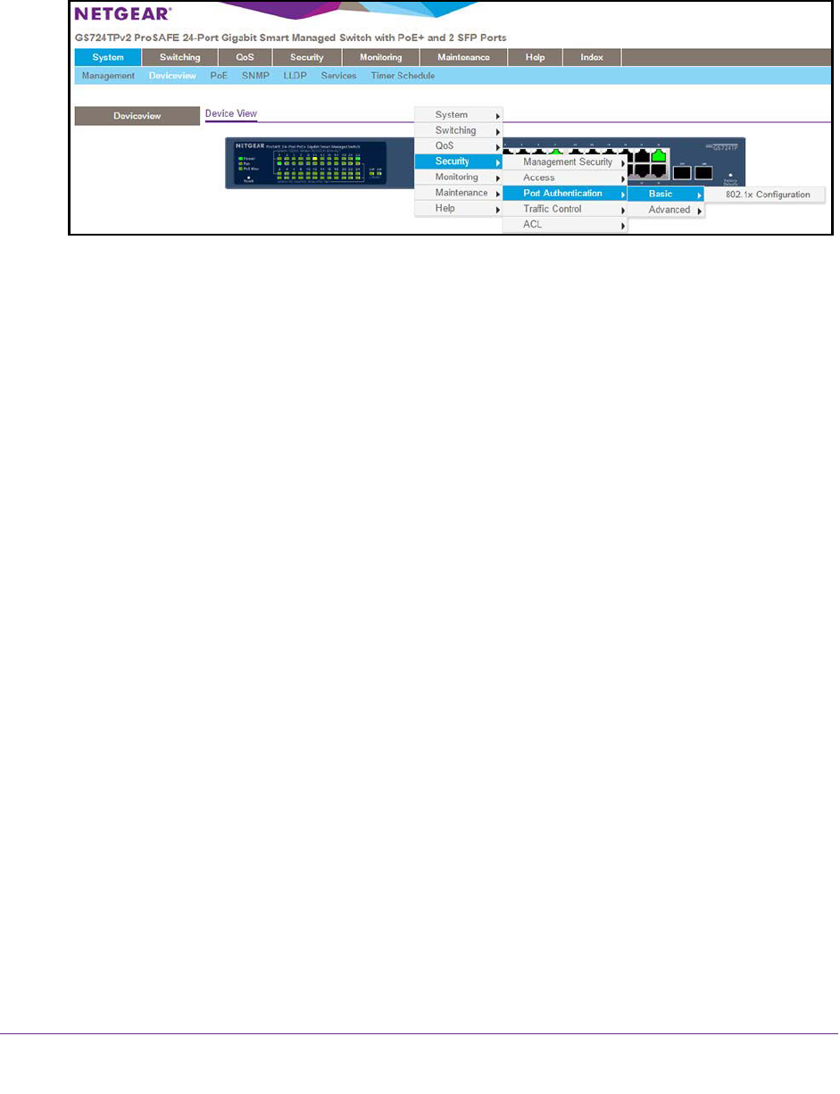
You can select a menu option to access the page that contains the configuration or
monitoring options.
If you right-click the graphic, but do not right-click a specific port, the main menu displays.
This menu contains the same options as the navigation tabs at the top of the page.
Right-click the specific port that you want to view or configure to see a menu that displays
statistics and configuration options. Select the menu option to access the page that
contains the configuration or monitoring options.
The system LEDs are located on the left side of the front panel.
Power LED
The Power LED is a bicolor LED that serves as an indicator of power and diagnostic status:
• Solid green. The power is supplied to the switch and operating normally.
• Solid yellow. The system is in the boot-up stage.
• Off. No power is supplied to the switch.
Fan LED
The Fan LED indicates the following status:
• Solid yellow. The fan is faulty.
• Off. The fan is operating normally.
PoE Max LED
The PoE Max LED indicates the following status:
• Solid amber. Less than 7W of PoE power is available.
• Blinking amber. At least once during the previous two minutes, less than 7W of PoE
power was available.
• Off. Sufficient (more than 7W of) PoE power is available.