
User Manual
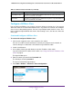


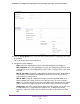
Table Of Contents
- 24-Port Gigabit Smart Managed Pro Switch with PoE+ and 2 SFP Ports Model GS724TPv2
- Contents
- 1. Get Started
- Switch Management Interface Overview
- Change the Default IP Address of the Switch
- Discover a Switch in a Network With a DHCP Server
- Discover a Switch in a Network Without a DHCP Server
- Configure the Network Settings on Your Computer
- Access the Web Browser–Based Management Interface
- About the User Interfaces
- Use a Web Browser to Access the Switch and Log In
- Web Browser–Based Management Interface Device View
- Interface Naming Conventions
- Configure Interface Settings
- Context-Sensitive Help and Access to the Support WebSite
- Register Your Product
- 2. Configure System Information
- 3. Configure Switching
- Configure Port Settings
- Configure Link Aggregation Groups
- Configure VLANs
- Configure a Voice VLAN
- Configure Auto-VoIP
- Configure Spanning Tree Protocol
- Configure Multicast
- View the MFDB Table
- View the MFDB Statistics
- IGMP Snooping Overview
- Configure IGMP Snooping
- Configure IGMP Snooping for Interfaces
- View the IGMP Snooping Table
- Configure IGMP Snooping for VLANs
- Modify IGMP Snooping Settings for a VLAN
- IGMP Snooping Querier Overview
- Configure IGMP Snooping Querier
- Configure IGMP Snooping Querier for VLANs
- Display IGMP Snooping Querier for VLAN Status
- Configure a Static Multicast Group
- Remove a Static Multicast Group
- Configure Multicast Group Membership
- Configure the Multicast Forward All Option
- View and Configure the MAC Address Table
- 4. Configure Quality of Service
- 5. Manage Device Security
- Configure the Management Security Settings
- Configure Management Access
- Configure Port Authentication
- Configure Traffic Control
- Configure Access Control Lists
- Use the ACL Wizard to Create a Simple ACL
- Configure a MAC ACL
- Configure MAC ACL Rules
- Configure MAC Bindings
- View or Delete MAC ACL Bindings in the MAC Binding Table
- Configure an IP ACL
- Configure Rules for a Basic IP ACL
- Configure Rules for an Extended IP ACL
- Configure IP ACL Interface Bindings
- View or Delete IP ACL Bindings in the IP ACL Binding Table
- 6. Monitor the System
- 7. Maintenance
- A. Configuration Examples
- B. Specifications and Default Settings

Configure Quality of Service
166
NETGEAR 24-Port Gigabit Smart Managed Pro Switch with PoE+ and 2 SFP Ports Model GS724TPv2
• Destination IP. Select this radio button to require a packet’s destination IP address to
match the specified IP address. After you select the radio button, use the following
fields to configure the destination IP address match criteria:
- Address. The destination IP address format to match in dotted-decimal.
- Mask. The bit mask in IP dotted-decimal format indicating which parts of the
destination IP address to use for matching against packet content.
• Destination L4 Port. Select this radio button to require a packet’s TCP/UDP
destination port to match the specified protocol, which you must select from the menu.
The menu includes Other as a selection, which lets you enter a destination port
number.
• IP DSCP. Select this radio button to require the packet’s IP DiffServ Code Point
(DSCP) value to match the specified IP DSCP keyword code, which you must select
from the menu. The menu includes Other as a selection, which lets you enter an IP
DSCP value from 0 to 63. The DSCP value is defined as the high-order 6 bits of the
Service Type octet in the IP header.
• Precedence Value. Select this radio button to require the packet’s IP precedence
value to match the specified number from 0 to 7, which you must select from the
menu. The IP Precedence field in a packet is defined as the high-order 3 bits of the
Service Type octet in the IP header.
• IP ToS. Select this radio button to require the packet’s Type of Service (ToS) bits in the
IP header to match the specified value. The IP ToS field in a packet is defined as all 8
bits of the service type octet in the IP header. After you select the radio button, use
the following fields to configure the ToS match criteria:
- Bits Value. Enter a two-digit hexadecimal number octet value in the range from 00
to ff to match the bits in a packet’s ToS field.
- Bit Mask. Specify the bit positions that are used for comparison against the IP ToS
field in a packet.
11. Click the Apply button.
The updated configuration is sent to the switch. Configuration changes take effect
immediately.
The following table describes the nonconfigurable information on the page.
Table 38. DiffServ Class Configuration, Class Summary information
Field Description
Match Criteria The configured match criteria for the specified class.
Values The values of the configured match criteria.