
User Manual


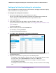


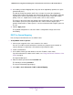
Table Of Contents
- 24-Port Gigabit Smart Managed Pro Switch with PoE+ and 2 SFP Ports Model GS724TPv2
- Contents
- 1. Get Started
- Switch Management Interface Overview
- Change the Default IP Address of the Switch
- Discover a Switch in a Network With a DHCP Server
- Discover a Switch in a Network Without a DHCP Server
- Configure the Network Settings on Your Computer
- Access the Web Browser–Based Management Interface
- About the User Interfaces
- Use a Web Browser to Access the Switch and Log In
- Web Browser–Based Management Interface Device View
- Interface Naming Conventions
- Configure Interface Settings
- Context-Sensitive Help and Access to the Support WebSite
- Register Your Product
- 2. Configure System Information
- 3. Configure Switching
- Configure Port Settings
- Configure Link Aggregation Groups
- Configure VLANs
- Configure a Voice VLAN
- Configure Auto-VoIP
- Configure Spanning Tree Protocol
- Configure Multicast
- View the MFDB Table
- View the MFDB Statistics
- IGMP Snooping Overview
- Configure IGMP Snooping
- Configure IGMP Snooping for Interfaces
- View the IGMP Snooping Table
- Configure IGMP Snooping for VLANs
- Modify IGMP Snooping Settings for a VLAN
- IGMP Snooping Querier Overview
- Configure IGMP Snooping Querier
- Configure IGMP Snooping Querier for VLANs
- Display IGMP Snooping Querier for VLAN Status
- Configure a Static Multicast Group
- Remove a Static Multicast Group
- Configure Multicast Group Membership
- Configure the Multicast Forward All Option
- View and Configure the MAC Address Table
- 4. Configure Quality of Service
- 5. Manage Device Security
- Configure the Management Security Settings
- Configure Management Access
- Configure Port Authentication
- Configure Traffic Control
- Configure Access Control Lists
- Use the ACL Wizard to Create a Simple ACL
- Configure a MAC ACL
- Configure MAC ACL Rules
- Configure MAC Bindings
- View or Delete MAC ACL Bindings in the MAC Binding Table
- Configure an IP ACL
- Configure Rules for a Basic IP ACL
- Configure Rules for an Extended IP ACL
- Configure IP ACL Interface Bindings
- View or Delete IP ACL Bindings in the IP ACL Binding Table
- 6. Monitor the System
- 7. Maintenance
- A. Configuration Examples
- B. Specifications and Default Settings

Configure Quality of Service
156
NETGEAR 24-Port Gigabit Smart Managed Pro Switch with PoE+ and 2 SFP Ports Model GS724TPv2
8. From the Interface Trust Mode menu, select one of the following trust mode options for
ingress traffic on the selected interfaces:
• Untrusted. Do not trust any CoS packet marking at ingress.
• 802.1p. The eight priority tags that are specified in IEEE 802.1p are p0 to p7. The
QoS setting lets you map each of the eight priority levels to one of seven internal
hardware priority queues. The default is 802.1p.
• DSCP. The six most significant bits of the DiffServ field are called the Differentiated
Services Code Point (DSCP) bits.
9. In the Interface Shaping Rate field, specify the maximum bandwidth allowed.
This is typically used to shape the outbound transmission rate in increments of 64 kbps in
the range 16 to 16384 kbps.This value is controlled independently of any per-queue
maximum bandwidth configuration. It is effectively a second-level shaping mechanism.
The default is 0. The value 0 means that the maximum is unlimited.
The expected shaping at egress interface is calculated as follows:
frameSize × shaping/(frameSize + IFG), where IFG (Inter frame gap) is 20 bytes,
frameSize is configured frame size, and shaping is configured traffic shaping.
For example, when 64 bytes frame size and 64 kbps shaping are configured, expected
shaping is approximately 48 kbps.
10. Click the Apply button.
The updated configuration is sent to the switch. Configuration changes take effect
immediately.
Configure CoS Queue Settings for an Interface
You can define what a particular queue does by configuring switch egress queues.
User-configurable parameters control the amount of bandwidth used by the queue, the queue
depth during times of congestion, and the scheduling of packet transmission from the set of
all queues on a port. Each port contains its own CoS queue-related configuration.
The configuration process is simplified by allowing each CoS queue parameter to be
configured globally or per port. A global configuration change is automatically applied to all
ports in the system.
To configure CoS queue settings for an interface:
1. Connect your computer to the same network as the switch.
You can use a WiFi or wired connection to connect your computer to the network, or
connect directly to a switch that is off-network using an Ethernet cable.
2. Launch a web browser.
3. In the address field of your web browser, enter the IP address of the switch.
If you do not know the IP address of the switch, see Change the Default IP Address of the
Switch on page 9.