
User Manual
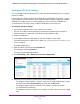

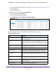


Table Of Contents
- 24-Port Gigabit Smart Managed Pro Switch with PoE+ and 2 SFP Ports Model GS724TPv2
- Contents
- 1. Get Started
- Switch Management Interface Overview
- Change the Default IP Address of the Switch
- Discover a Switch in a Network With a DHCP Server
- Discover a Switch in a Network Without a DHCP Server
- Configure the Network Settings on Your Computer
- Access the Web Browser–Based Management Interface
- About the User Interfaces
- Use a Web Browser to Access the Switch and Log In
- Web Browser–Based Management Interface Device View
- Interface Naming Conventions
- Configure Interface Settings
- Context-Sensitive Help and Access to the Support WebSite
- Register Your Product
- 2. Configure System Information
- 3. Configure Switching
- Configure Port Settings
- Configure Link Aggregation Groups
- Configure VLANs
- Configure a Voice VLAN
- Configure Auto-VoIP
- Configure Spanning Tree Protocol
- Configure Multicast
- View the MFDB Table
- View the MFDB Statistics
- IGMP Snooping Overview
- Configure IGMP Snooping
- Configure IGMP Snooping for Interfaces
- View the IGMP Snooping Table
- Configure IGMP Snooping for VLANs
- Modify IGMP Snooping Settings for a VLAN
- IGMP Snooping Querier Overview
- Configure IGMP Snooping Querier
- Configure IGMP Snooping Querier for VLANs
- Display IGMP Snooping Querier for VLAN Status
- Configure a Static Multicast Group
- Remove a Static Multicast Group
- Configure Multicast Group Membership
- Configure the Multicast Forward All Option
- View and Configure the MAC Address Table
- 4. Configure Quality of Service
- 5. Manage Device Security
- Configure the Management Security Settings
- Configure Management Access
- Configure Port Authentication
- Configure Traffic Control
- Configure Access Control Lists
- Use the ACL Wizard to Create a Simple ACL
- Configure a MAC ACL
- Configure MAC ACL Rules
- Configure MAC Bindings
- View or Delete MAC ACL Bindings in the MAC Binding Table
- Configure an IP ACL
- Configure Rules for a Basic IP ACL
- Configure Rules for an Extended IP ACL
- Configure IP ACL Interface Bindings
- View or Delete IP ACL Bindings in the IP ACL Binding Table
- 6. Monitor the System
- 7. Maintenance
- A. Configuration Examples
- B. Specifications and Default Settings
Configure Switching
122
NETGEAR 24-Port Gigabit Smart Managed Pro Switch with PoE+ and 2 SFP Ports Model GS724TPv2
7. From the STP Status menu, select the option to enable or disable the spanning tree
administrative mode that is associated with the port or port channel.
The possible values are Enable and Disable. The default is Enable.
8. From the Fast Link menu, select whether the specified port is an edge port within the CST.
The possible values are Enable and Disable. The default is Enable.
9. In the Path Cost field, set the path cost to a new value for the specified port in the common
and internal spanning tree.
Specify a value in the range of 0 to 200000000. The default is 0. When the path cost is set
to 0, the value is updated with the external path cost from a received STP packet.
10. In the Priority field, specify the priority for a particular port within the CST.
The port priority is set in multiples of 16. For example if you attempt to set the priority to
any value between 0 and 15, it is set to 0. If you try to set it to any value between 16 and
(2*16 – 1), it is set to 16, and so on. The range is 0 to 240. The default is 128.
11. Click the Apply button.
The updated configuration is sent to the switch. Configuration changes take effect
immediately.
12. To refresh the page with the latest information about the switch, click the Update button.
The following table describes the nonconfigurable information on the page.
View CST Port Status
You can display Common Spanning Tree (CST) and Internal Spanning Tree on a specific port
on the switch.
To view the CST port status:
1. Connect your computer to the same network as the switch.
You can use a WiFi or wired connection to connect your computer to the network, or
connect directly to a switch that is off-network using an Ethernet cable.
2. Launch a web browser.
3. In the address field of your web browser, enter the IP address of the switch.
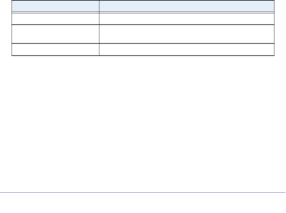
Table 24. CST port configuration
Field Description
Port State The forwarding state of this port. The default is Disabled.
Port ID The port identifier for the specified port within the CST. It is made up
from the port priority and the interface number of the port.
Hello Timer The value of the parameter for the CST. The default is 2 seconds.