
User Manual
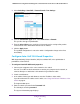
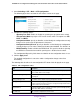


Table Of Contents
- 24-Port Gigabit Smart Managed Pro Switch with PoE+ and 2 SFP Ports Model GS724TPv2
- Contents
- 1. Get Started
- Switch Management Interface Overview
- Change the Default IP Address of the Switch
- Discover a Switch in a Network With a DHCP Server
- Discover a Switch in a Network Without a DHCP Server
- Configure the Network Settings on Your Computer
- Access the Web Browser–Based Management Interface
- About the User Interfaces
- Use a Web Browser to Access the Switch and Log In
- Web Browser–Based Management Interface Device View
- Interface Naming Conventions
- Configure Interface Settings
- Context-Sensitive Help and Access to the Support WebSite
- Register Your Product
- 2. Configure System Information
- 3. Configure Switching
- Configure Port Settings
- Configure Link Aggregation Groups
- Configure VLANs
- Configure a Voice VLAN
- Configure Auto-VoIP
- Configure Spanning Tree Protocol
- Configure Multicast
- View the MFDB Table
- View the MFDB Statistics
- IGMP Snooping Overview
- Configure IGMP Snooping
- Configure IGMP Snooping for Interfaces
- View the IGMP Snooping Table
- Configure IGMP Snooping for VLANs
- Modify IGMP Snooping Settings for a VLAN
- IGMP Snooping Querier Overview
- Configure IGMP Snooping Querier
- Configure IGMP Snooping Querier for VLANs
- Display IGMP Snooping Querier for VLAN Status
- Configure a Static Multicast Group
- Remove a Static Multicast Group
- Configure Multicast Group Membership
- Configure the Multicast Forward All Option
- View and Configure the MAC Address Table
- 4. Configure Quality of Service
- 5. Manage Device Security
- Configure the Management Security Settings
- Configure Management Access
- Configure Port Authentication
- Configure Traffic Control
- Configure Access Control Lists
- Use the ACL Wizard to Create a Simple ACL
- Configure a MAC ACL
- Configure MAC ACL Rules
- Configure MAC Bindings
- View or Delete MAC ACL Bindings in the MAC Binding Table
- Configure an IP ACL
- Configure Rules for a Basic IP ACL
- Configure Rules for an Extended IP ACL
- Configure IP ACL Interface Bindings
- View or Delete IP ACL Bindings in the IP ACL Binding Table
- 6. Monitor the System
- 7. Maintenance
- A. Configuration Examples
- B. Specifications and Default Settings
Configure Switching
118
NETGEAR 24-Port Gigabit Smart Managed Pro Switch with PoE+ and 2 SFP Ports Model GS724TPv2
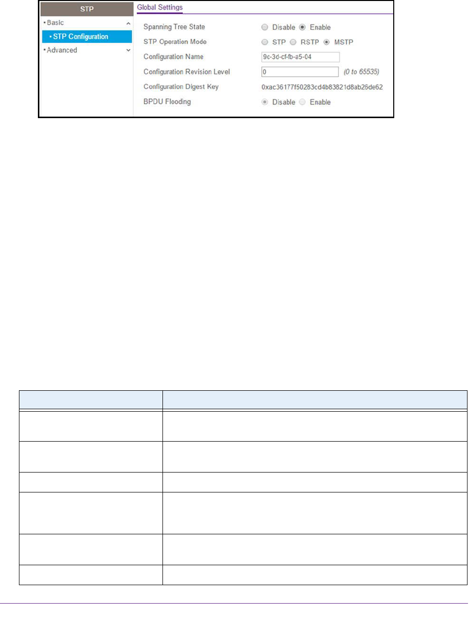
5. Select Switching > STP > Basic > STP Configuration.
The following figure does not show the STP Status section on the page.
6. Configure the following options:
• Spanning Tree State. Enable or disable the spanning tree operation on the switch.
• STP Operation Mode. Specify the STP version for the switch. The options are STP,
RSTP, and MSTP.
• Configuration Name. Specify an identifier used to identify the configuration currently
being used. It can be up to 32 alphanumeric characters.
• Configuration Revision Level. Specify an identifier used to identify the configuration
currently being used. The values allowed are between 0 and 65535. The default is 0.
• BPDU Flooding. Enable or disable the BPDU flood. This specifies whether spanning
tree BPDUs are forwarded or not while spanning tree is disabled on the switch.
The Configuration Digest Key field shows the identifier for the configuration that is in use.
7. Click the Apply button.
The updated configuration is sent to the switch. Configuration changes take effect
immediately.
The following table describes the nonconfigurable STP Status fields displayed on the page.
Table 23. STP configuration status
Field Description
Bridge Identifier The bridge identifier for the CST. It is made up using the bridge priority and
the base MAC address of the bridge.
Time Since Topology Change The time in day-hour-minute-second format since the topology of the CST
last changed.
Topology Change Count The number of times that the topology changed for the CST.
Topology Change The value of the topology change parameter for the switch indicating
whether a topology change is in progress on any port assigned to the CST.
Possible values are True and False.
Designated Root The bridge identifier of the root bridge. It is made up from the bridge priority
and the base MAC address of the bridge.
Root Path Cost Path cost to the designated root for the CST.