GS700AT Series Smart Switch Software Administration Manual NETGEAR, Inc.
GS700AT Series Smart Switch Software Administration Manual © 2007, 2008 by NETGEAR, Inc. All Rights reserved. Trademarks NETGEAR and the NETGEAR logo are registered trademarks of NETGEAR, Inc. in the United States and/or other countries. Microsoft, Windows, and Windows NT are registered trademarks and Vista is a trademark of Microsoft Corporation. Other brand and product names are trademarks or registered trademarks of their respective holders.
GS700AT Series Smart Switch Software Administration Manual • • • • Reorient or relocate the receiving antenna. Increase the separation between the equipment and receiver. Connect the equipment into an outlet on a circuit different from that which the receiver is connected. Consult the dealer or an experienced radio/TV technician for help. EU Statement of Compliance The NETGEAR GS700AT Series Gigabit Smart Switch is compliant with the following EU Council Directives: 89/336/ EEC and LVD 73/23/EEC.
GS700AT Series Smart Switch Software Administration Manual the radiator and your body. This transmitter must not be co-located or operating in conjunction with any other antenna or transmitter. FCC Declaration Of Conformity: We, NETGEAR, Inc., 4500 Great America Parkway, Santa Clara, CA 95054, declare under our sole responsibility that the model GS700AT Series Gigabit Smart Switch complies with Part 15 of FCC Rules.
Contents About This Manual Who Should Use this Book ............................................................................................... ix How to Use This Book ...................................................................................................... ix Conventions, Formats, and Scope .................................................................................... x How to Use This Manual ...........................................................................................
GS700AT Series Smart Switch Software Administration Manual Ports ...............................................................................................................................4-1 LAG ................................................................................................................................4-4 VLAN ............................................................................................................................4-14 Voice VLAN ...................................
Smart Switch Software Administration Manual Support ...........................................................................................................................9-1 User Guide .....................................................................................................................9-2 Appendix A Default Settings Index Contents vii v1.
GS700AT Series Smart Switch Software Administration Manual viii Contents v1.
About This Manual The NETGEAR® GS700AT Series Smart Switch Software Administration Manual describes how to install, configure, operate, and troubleshoot the GS700AT Gigabit Smart Switch using its included software. This book describes the software configuration procedures and explains the options available within those procedures. Who Should Use this Book The information in this manual is intended for readers with intermediate to advanced system management skills.
GS700AT Series Smart Switch Software Administration Manual • Chapter 6, “Managing Security” describes how to configure security. • Chapter 7, “Monitoring the Switch” describes how to configure switch monitoring. • Chapter 8, “Maintenance” describes the firmware upgrade procedure and reset functions. • Chapter 9, “Online Help” describes how to obtain online help and support. • Appendix A, “Default Settings” gives GS700AT Series Smart Switch specifications and lists default feature values.
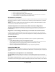
GS700AT Series Smart Switch Software Administration Manual Danger: This is a safety warning. Failure to take heed of this notice may result in personal injury or death. • Scope. This manual is written for the GS700AT Series Smart Switch according to these specifications: Product Version GS700AT Gigabit Smart Switch Manual Publication Date March 2008 . Note: Product updates are available on the NETGEAR, Inc. website at http://www.netgear.com/support.
GS700AT Series Smart Switch Software Administration Manual How to Print this Manual To print this manual, select one of the following options: • Printing a Page from HTML. Each page in the HTML version of the manual is dedicated to a major topic. Select File > Print from the browser menu to print the page contents. • Printing from PDF. Your computer must have the free Adobe Acrobat reader installed in order to view and print PDF files. The Acrobat reader is available on the Adobe Web site at http://www.
GS700AT Series Smart Switch Software Administration Manual xiii v1.
Chapter 1 Getting Started with Switch Management This section provides an overview of switch management, including the methods you can choose to start managing your NETGEAR GS700AT Gigabit Smart Switch. It also leads you through the steps necessary to get started, using the SmartWizard Discovery utility.
GS700AT Series Smart Switch Software Administration Manual Note: For complete hardware installation instructions, refer to the GS700AT Series Smart Switch Hardware Installation Manual included on your Resource CD, or go to http://www.netgear.com/support. Switch Management Interface Your NETGEAR GS700AT Gigabit Smart Switch contains an embedded web server and management software for managing and monitoring switch functions. This switch operates as a simple switch without using the management software.
GS700AT Series Smart Switch Software Administration Manual Table 1-1.
GS700AT Series Smart Switch Software Administration Manual 5. Click Discover for the SmartWizard Discovery utility to find your GS700AT Gigabit Smart Switch. You should see a screen similar to that shown below. Figure 1-1 6. Note the displayed IP address assigned by the DHCP server. You will need this value to access the switch directly from a web browser (without using the SmartWizard Discovery utility). 7. Select your switch by highlighting the name of the switch. Then click Web Access.
GS700AT Series Smart Switch Software Administration Manual 8. Use your web browser to manage your switch. The default password is password. Then use this screen to proceed to management of the switch covered in Chapter 2, “Introduction to the Web Browser Interface”.
GS700AT Series Smart Switch Software Administration Manual 6. Click Configuration Setting. A screen similar to that shown below appears. Figure 1-3 7. Select Disable to disable DHCP. 8. The default IP address is 192.168.0.239 and the default subnet mask is 255.255.255.0. If you want different values, enter the switch IP address, gateway IP address and subnet mask. 9. Type your password and click Set. Please ensure that your PC and the GS700AT Gigabit Smart Switch are in the same subnet.
GS700AT Series Smart Switch Software Administration Manual NIC Setting on the Host that Accesses the GS700AT Gigabit Smart Switch The settings of your Network Interface Card (NIC) under MS Windows OS are made with entries into Windows screens similar to the ones shown below. For comparison, the settings screens of the switch are also shown although they do not appear in the Windows view. Figure 1-4 You need Windows Administrator privileges to change these settings. 1.
GS700AT Series Smart Switch Software Administration Manual Web Access For Web access, you can either: • Select Web Access using the SmartWizard Discovery utility (see “Network with a DHCP Server” or “Network without a DHCP Server”). • Access the switch directly, without using the SmartWizard Discovery utility. You must work from the same network segment that contains the switch (i.e.
GS700AT Series Smart Switch Software Administration Manual Additional Utilities Alternatively, from the main screen shown on Figure 1-1 you can access these additional functions: • “Password Change” • “Firmware Upgrade” Password Change You can set a new password of up to 20 ASCII characters. 1. Click Password Change from the Switch Setting section. The Password Change screen appears. You can set a new password. You must enter the old and new passwords and confirm the new one. 2.
GS700AT Series Smart Switch Software Administration Manual If you click Firmware Upgrade from the main screen (see Figure 1-1), after you have selected the switch to upgrade, the following screen appears: Figure 1-6 1. Enter the following values into the appropriate places in the form: • Product Assigned Firmware: The location of the new firmware. If you do not know the location, click Browse to locate the file. • Upgrade Password: Enter your password; the default password is password. 2.
Chapter 2 Introduction to the Web Browser Interface This section introduces the web browser interface that enables you to configure and manage your NETGEAR GS700AT Gigabit Smart Switch. Your GS700AT Series Smart Switch provides a built-in browser interface that enables you to configure and manage it remotely using a standard Web browser such as Microsoft Internet Explorer or Netscape Navigator. Online Help is also provided for many of the basic functions and features of the switch.
GS700AT Series Smart Switch Software Administration Manual 2. Enter the password (the factory default is password) and click Login. The home screen of the GS700AT Series Smart Switch browser interface displays. The Navigation Menu As shown below, logging in brings you to the view of the web browser interface.
GS700AT Series Smart Switch Software Administration Manual Work Area – Located on the right side of the NETGEAR GS700AT Series web browser interface and marked as 3 in Figure 2-2. The Work Area contains device tables, general device information, and configurable device parameters. For further description of the functions, refer to the appropriate section of this manual: • Chapter 3, “Managing System Settings” describes how to configure the System functions.
GS700AT Series Smart Switch Software Administration Manual Table 2-1. Device Management Buttons (continued) Button Name Description CLEAR ALL Refreshes device information. CLEAR ALL COUNTERS Resets statistics counters. CLEAR LOGS Clears logs. CURRENT MEMBERS Displays current members of a LAG. DELETE Deletes information from tables or information windows. GO Selects the specified interface. REFRESH Refreshes the screen with current data.
GS700AT Series Smart Switch Software Administration Manual To access the help file for a screen: 1. Click the encircled red Question Mark icon, shown in the example below. Figure 2-3 A help window for the screen opens. Figure 2-4 Using Screen and Table Options The NETGEAR GS700AT Series web browser interface contains screens and tables for configuring devices.
GS700AT Series Smart Switch Software Administration Manual Selecting an Entry To select an entry: 1. Check the entry’s Select box. The selected entry is highlighted and the information appears in the first row, which contains the editable fields. Figure 2-5 To select all entries: 1. Check the Select box in the first row to select all entries in the table. Fields that are unique are grayed out and displayed as read-only fields.
GS700AT Series Smart Switch Software Administration Manual To add an entry by creating a new entry in the table: 1. Enter the fields for the new entry in the provided fields in the first row. Figure 2-7 2. Click ADD to update the device. The new entry is displayed. Figure 2-8 Modifying an Entry An entry may be modified by editing its values in the first row. To modify an entry: 1. Select the entry to be modified. Its contents are displayed in the first row. Figure 2-9 2.
GS700AT Series Smart Switch Software Administration Manual Deleting an Entry To delete entries from a table: 1. Select the entries to be deleted. 2. Click DELETE to update the device. Special Table Options The NETGEAR web browser interface tables have a unique GUI design which includes the following options: • Gold Buttons • Quick Boxes • Interface View and Selection Gold Buttons. Gold Buttons provide flexibility in viewing and configuring VLANs/LAGs on a port level.
GS700AT Series Smart Switch Software Administration Manual To mark or unmark all ports: 1. Click on the quick box that appears to the left of the Port gold button. A T appears in the quick box. This sets all ports as Tagged. Figure 2-11 2. Click on the Port gold button to display the ports, which are now all Tagged. Figure 2-12 3. Click again on the Port quick box, and a U appears in the quick box and in all the port boxes, marking the ports as untagged. Figure 2-13 4.
GS700AT Series Smart Switch Software Administration Manual 5. You may click on individual port boxes to toggle their tagged/untagged status Interface View and Selection. A port or LAG interface may be selected from a table by using the interface selection row, located above the row of column headers. Clicking on PORTS or LAGS displays the ports or the LAGs: Figure 2-14 To display all ports: 1. Click PORTS in the interface selection row. The screen displays a table of all ports.
GS700AT Series Smart Switch Software Administration Manual 3. Click OK. The screen displays a table of all interfaces. To display the LAG table: 1. Click LAGS in the interface selection row. The screen displays a table of all LAGs. Figure 2-16 To select an interface: 1. Enter the number of the interface in the GO TO INTERFACE box. 2. Click GO to select the interface, as in the following example. Figure 2-17 Introduction to the Web Browser Interface v1.
GS700AT Series Smart Switch Software Administration Manual 2-12 Introduction to the Web Browser Interface v1.
Chapter 3 Managing System Settings Using the System Settings Utility The navigation pane at the top of the web browser interface contains a System tab that enables you to manage your GS700AT Series Smart Switch with features under the following main menu options: • “Management” • “Device View” • “SNMP” • “LLDP” The description that follows in this chapter describes configuring and managing system settings in the GS700AT Series Smart Switch.
GS700AT Series Smart Switch Software Administration Manual To configure system parameters: 1. Click System > Management > System Information. The System Information screen displays: Figure 3-1 The System Information screen contains the following fields: • System Name – Enter the user-defined device name. The field may contain 0-160 characters. • System Location – Enter the location where the system is currently running. The field may contain 0-160 characters.
GS700AT Series Smart Switch Software Administration Manual • Jumbo Frames Status – Displays the Jumbo Frame status. • Jumbo Frames After Reset – Select the Jumbo Frame status. The possible field values are: – Enable – Enable Jumbo Frames. – Disable – Disable Jumbo Frames. The Versions Table displays the following fields: • Model Name – Displays the device model name. • Hardware Version – Displays the installed device hardware version number.
GS700AT Series Smart Switch Software Administration Manual To define an IP interface: 1. Click System > Management > IP Configuration. The IP Configuration screen displays: Figure 3-2 The IP Configuration screen contains the following fields: • Dynamic IP Address (DHCP) – Enable the IP address to be configured automatically by the DHCP server. Selecting this field disables the IP Address, Subnet Mask, Gateway and Delete fields. • Static IP Address – Enable the user to define a static IP address.
GS700AT Series Smart Switch Software Administration Manual Time Configuration The Time Configuration screen contains information for defining both the local hardware clock and the external SNTP clock. If the system time is managed via an external SNTP clock, and the external SNTP clock fails, the system time reverts to the local hardware clock. To configure the local system time: 1. Click System > Management > Time > Time Configuration.
GS700AT Series Smart Switch Software Administration Manual 5. Click Apply to update the system settings. Note: If you selected SNTP, you must configure the SNTP servers. See “SNTP Server Configuration” for detailed instructions on configuring the SNTP servers. SNTP Server Configuration The SNTP Server Configuration screen allows network administrators to define primary and secondary SNTP servers. The system time is first retrieved through the primary SNTP server.
GS700AT Series Smart Switch Software Administration Manual To remove SNTP servers: 1. Check the Delete box for each SNTP server that is to be removed. 2. Click Apply to update the system settings. Device View The Device View menu option displays the Device View screen, which provides a graphic representation of the device, including the port and LED statuses. To display the Device View screen: 1. Click System > Device View.
GS700AT Series Smart Switch Software Administration Manual • Authentication – Provides data integrity and data origin authentication. • Privacy – Protects against the disclosure of message content. Cipher Block-Chaining (CBC) is used for encryption. Either authentication is enabled on an SNMP message, or both authentication and privacy. However, privacy cannot be enabled without authentication. • Timeliness – Protects against message delay or message redundancy.
GS700AT Series Smart Switch Software Administration Manual To configure SNMP communities: 1. Click System > SNMP > SNMPv1/v2 > Community Configuration. The Community Configuration screen displays: Figure 3-6 The SNMPv1/v2 Community Configuration screen contains the following fields: • Management Station – Enter the management station IP address for which the Basic SNMP community is defined. • Community String – Enter the SNMP community string used to authenticate the management station to the device.
GS700AT Series Smart Switch Software Administration Manual 2. Enter the Management Station and Community String in the provided fields in the first row. 3. Select the Access Mode from the list in the provided field in the first row. 4. Click Add to update the device. To remove an SNMP community: 1. Click System > SNMP > SNMPv1/v2 > Community Configuration. The Community Configuration screen displays. 2. Select the entry to be removed. 3. Click Delete to remove the entry.
GS700AT Series Smart Switch Software Administration Manual • Notification Type – (Configurable only if the Notification Version is SNMPv2.) Select the type of notification sent. The possible field values are: – Traps – Traps are sent. – Informs – Informs are sent only when SNMPv2 is enabled. • Community String – Enter the community string of the trap manager. • Notification Version – Select the trap type. The possible field values are: – SNMPv1 – SNMP Version 1 traps are sent.
GS700AT Series Smart Switch Software Administration Manual • “View Name” • “View Content” • “Community Configuration” • “Group Configuration” • “User Configuration” • “Global Trap Configuration” • “Trap Configuration” • “Trap Filter Name” • “Trap Filter Content” Engine ID The SNMPv3 Engine ID screen allows network managers to define the SNMP Engine ID and to assign the default parameters to SNMP. To define the Local Engine ID: 1. Click System > SNMP > SNMPv3 > Engine ID.
GS700AT Series Smart Switch Software Administration Manual • Use Default – Check the box to use the device-generated Engine ID. The default Engine ID is based on the device MAC address and is defined per standard as: – First 4 octets – First bit = 1, the rest is the IANA Enterprise number. – Fifth octet – Set to 3 to indicate the MAC address that follows. – Last 6 octets – MAC address of the device. 2.
GS700AT Series Smart Switch Software Administration Manual To add a new SNMP View Name: 1. Click System > SNMP > SNMPv3 > View Name. The SNMPv3 View Name screen displays. 2. Enter the View Name field in the first row. 3. Click Add to update the device. To remove an SNMP View Name: 1. Click System > SNMP > SNMPv3 > View Name. The SNMPv3 View Name screen displays. 2. Select the entry to be removed. 3. Click Delete to remove the entry.
GS700AT Series Smart Switch Software Administration Manual • Object ID Subtree – Enter the device feature OID. • View Type – Select whether the defined OID branch will be included in or excluded from the selected SNMP view. The possible field values are: – Included – The OID is included in the SNMP view. – Excluded – The OID is excluded from the SNMP view. 2. Select the View Name from the list in the provided field in the Views table. 3.
GS700AT Series Smart Switch Software Administration Manual To define SNMPv3 communities: 1. Click System > SNMP > SNMPv3 > Community Configuration. The SNMPv3 Community Configuration screen displays: Figure 3-11 The SNMPv3 Community Configuration screen contains the following fields: • Management Station – Enter the management station IP address for which the SNMP community is defined. • Community String – Enter the password used to authenticate the management station to the device.
GS700AT Series Smart Switch Software Administration Manual To remove an SNMPv3 community: 1. Click System > SNMP > SNMPv3 > Community Configuration. The SNMPv3 Community Configuration screen displays. 2. Select the community entry. 3. Click Delete to remove the entry. Group Configuration The SNMPv3 Groups screen provides information for creating SNMP groups and assigning SNMP access control privileges to SNMP groups.
GS700AT Series Smart Switch Software Administration Manual • • Security Level – Select the security level attached to the group. Security levels apply to SNMPv3 only. The possible field values are: – No Authentication – Neither the Authentication nor the Privacy security levels are assigned to the group. – Authentication – Authenticates SNMP messages and ensures that the SNMP message’s origin is authenticated. – Privacy – Encrypts SNMP messages. Operation – Select the group access rights.
GS700AT Series Smart Switch Software Administration Manual 3. Click Delete to remove the entry. User Configuration The SNMPv3 User Configuration screen provides information for creating SNMP groups and assigning SNMP access control privileges to SNMP groups. Groups allow network managers to assign access rights to specific device features or feature aspects. To define SNMP users: 1. Click System > SNMP > SNMPv3 > User Configuration.
GS700AT Series Smart Switch Software Administration Manual – SHA Password – Users are authenticated using the HMAC-SHA-96 authentication level. The user must enter a password. – None – No user authentication is used. • Password (1-32 Characters) – Enter the password for the group member. • Authentication Key – Enter the HMAC-MD5-96 or HMAC-SHA-96 authentication level. The authentication and privacy keys are entered to define the authentication key.
GS700AT Series Smart Switch Software Administration Manual To remove an SNMPv3 user: 1. Click System > SNMP > SNMPv3 > Users Configuration. The SNMPv3 User Configuration screen displays. 2. Select the user entry. 3. Click Delete to remove the entry. Global Trap Configuration The SNMPv3 Global Trap Settings screen contains parameters for defining SNMP notification parameters. To configure SNMP notification global parameters: 1. Click System > SNMP > SNMPv3 > Global Trap Configuration.
GS700AT Series Smart Switch Software Administration Manual – Disable – Disable the device from sending authentication failure notifications. 2. Select either Enable or Disable in the SNMP Notifications provided field. 3. Select either Enable or Disable in the Authentication Notifications provided field. 4. Click Apply to update the device.
GS700AT Series Smart Switch Software Administration Manual – Informs – Informs are sent. • User Name – Enter the user name. The field range is up to 30 alphanumeric characters. • Security Level – Select the security level attached to the group. Security levels apply to SNMPv3 only. The possible field values are: – No Authentication – Neither the Authentication nor the Privacy security levels are assigned to the group.
GS700AT Series Smart Switch Software Administration Manual 6. Enter the UDP Port in the provided field in the first row. 7. Select the Filter Name from the list in the provided field in the first row. 8. Enter the Timeout and Retries in the provided fields in the first row. 9. Click Add to update the device. To remove a trap: 1. Click System > SNMP > SNMPv3 > Trap Configuration. The SNMPv3 Trap Configuration screen displays. 2. Select the trap entry. 3. Click Delete to remove the entry.
GS700AT Series Smart Switch Software Administration Manual 3. Enter the trap Filter Name in the provided field in the first row. 4. Click Apply to update the device. To add a new trap filter name: 1. Click System > SNMP > SNMPv3 > Trap Filter Name. The SNMPv3 Trap Filter Name screen displays. 2. Enter the trap Filter Name in the provided field in the first row. 3. Click Add to update the device. To remove a trap filter name: 1. Click System > SNMP > SNMPv3 > Trap Filter Name.
GS700AT Series Smart Switch Software Administration Manual Trap Filter Settings • Filter Name – Select the user-defined notification filter from the list. Trap Filter Settings • Object ID Subtree – Enter the OID for which notifications are sent or blocked. If a filter is attached to an OID, traps or informs are generated and sent to the trap recipients. OIDs are selected from either the Select field or the Object ID field.
GS700AT Series Smart Switch Software Administration Manual LLDP The Link Layer Discovery Protocol (LLDP) allows network managers to troubleshoot and enhance network management by discovering and maintaining network topologies over multivendor environments. LLDP discovers network neighbors by standardizing methods for network devices to advertise themselves to other system, and to store discovered information.
GS700AT Series Smart Switch Software Administration Manual To configure LLDP settings: 1. Click System > LLDP > Basic > LLDP Configuration. The Basic LLDP Configuration screen displays: Figure 3-18 The Basic LLDP Configuration screen contains the following fields: LLDP Properties • • LLDP – Select the LLDP global status on the device. The possible field values are: – Disable – Disable LLDP on the device. This is the default value. – Enable – Enable LLDP on the device.
GS700AT Series Smart Switch Software Administration Manual • Reinitializing Delay – Enter the amount of time in seconds that passes between disabling and reinitializing LLDP. The possible field range is 1 - 10 seconds. The field default is 2 seconds. • Transmit Delay – Enter the amount of time in seconds that passes between successive LLDP frame transmissions due to changes in the LLDP local systems MIB. The possible field value is 1 - 8192 seconds. The field default is 2 seconds.
GS700AT Series Smart Switch Software Administration Manual To configure LLDP settings: 1. Click System > LLDP > Advanced > LLDP Configuration. The Advanced LLDP Configuration screen displays: Figure 3-19 The Advanced LLDP Configuration screen contains the following fields: LLDP Properties • • LLDP – Select the LLDP global status on the device. The possible field values are: – Disable – Disable LLDP on the device. This is the default value. – Enable – Enable LLDP on the device.
GS700AT Series Smart Switch Software Administration Manual • Reinitializing Delay – Enter the amount of time in seconds that passes between disabling and reinitializing LLDP. The possible field range is 1 - 10 seconds. The field default is 2 seconds. • Transmit Delay – Enter the amount of time in seconds that passes between successive LLDP frame transmissions due to changes in the LLDP local systems MIB. The possible field value is 1 - 8192 seconds. The field default is 2 seconds.
GS700AT Series Smart Switch Software Administration Manual To define LLDP Port Properties: 1. Click System > LLDP > Advanced > LLDP Port Settings. The LLDP Port Settings screen displays: Figure 3-20 The LLDP Port Settings screen contains the following fields: • Interface – Displays the specific interface for which LLDP parameters are defined. • Admin Status – Select the LLDP packet transmitting and receiving status of the interface.
GS700AT Series Smart Switch Software Administration Manual – • • AutoAdvertise – Advertise the device’s current IP address as the management IP address. Notification – Select the topology change notification status on the interface. – Enable – Enable topology change notification on the interface. This is the default value. – Disable – Disable topology change notification on the interface. Optional TLVs – Select whether optional TLVs are advertised from the interface.
GS700AT Series Smart Switch Software Administration Manual The LLDP-MED Network Policy screen allows network administrators to define LLDP-MED network policies, which include the application, VLAN ID, VLAN type, user priority and DSCP value. To configure LLDP-MED Network Policy: 1. Click System > LLDP > Advanced > LLDP-MED Network Policy.
GS700AT Series Smart Switch Software Administration Manual • VLAN Type – Select the VLAN type for which the network policy is defined. The possible field values are: – Tagged – The network policy is defined for tagged VLANs. – Untagged – The network policy is defined for untagged VLANs. • User Priority – Select the priority assigned to the network application. The field range is 0 - 7. • DSCP Value – Select the DSCP value assigned to the network policy. The possible field value is 0 - 63. 2.
GS700AT Series Smart Switch Software Administration Manual LLDP-MED Port Settings The LLDP-MED Port Settings screen contains parameters for assigning LLDP-MED network policies to specific ports. To configure LLDP-MED port settings: 1. Click System > LLDP > Advanced > LLDP-MED Port Settings. The LLDP-MED Port Settings screen displays: Figure 3-22 The LLDP-MED Port Settings screen contains the following fields: • Port – Select the port to configure.
GS700AT Series Smart Switch Software Administration Manual 4. Select the Notification Status of the selected port from the list in the provided field. 5. Click on the Network Policies gold bar and select the network policy numbers to apply to the port. 6. Click Apply to update the device. Local Information The LLDP Local Information screen enables viewing detailed port LLDP-MED information. To view LLDP-MED port information: 1. Click System > LLDP > Advanced > Local Information.
GS700AT Series Smart Switch Software Administration Manual • System Name – Displays the administratively assigned device name. • System Description – Describes the device. For example, system hardware type and version, operating system and network software. • System Capabilities – Describes the primary device function. For example: Bridge, Router. Port Information • Interface – Displays the port number. • Port ID Subtype – Displays the port ID type. For example, MAC address.
GS700AT Series Smart Switch Software Administration Manual 2. Click the Interface to view its detailed information. The Port Information window opens: Figure 3-24 The Port Information window contains the following fields: Managed Address • Address Subtype – Displays the managed address subtype. For example, IPv4. • Address – Displays the managed address. • Interface Subtype – Displays the port subtype. • Interface Number – Displays the port number.
GS700AT Series Smart Switch Software Administration Manual – Enabled – Auto-negotiation is enabled on the port. – Disabled – Auto-negotiation is not enabled on the port. • Auto-Negotiation Advertised Capabilities – Displays the port speed auto-negotiation capabilities. For example, 1000BASE-T half duplex mode, 100BASE-TX full duplex mode. • Operational MAU Type – Displays the Medium Attachment Unit (MAU) type.
GS700AT Series Smart Switch Software Administration Manual To view LLDP neighbors information: 1. Click System > LLDP > Advanced > Neighbors Information. The LLDP Neighbors Information screen displays: Figure 3-25 The LLDP Neighbors Information screen contains the following fields: • MSAP Entry – Displays the device’s Media Service Access Point (MSAP) entry number. • Local Port – Displays the port number. • Chassis ID Subtype – Displays the chassis ID subtype. For example, MAC address.
GS700AT Series Smart Switch Software Administration Manual 2. Click the MSAP Entry to view its detailed information. The Neighbors Information window opens: Figure 3-26 3-42 Managing System Settings v1.
GS700AT Series Smart Switch Software Administration Manual The Neighbors Information window contains the following fields: Port Details • Local Port – Displays the port number. • MSAP Entry – Displays the device’s Media Service Access Point (MSAP) entry number. Basic Details • Chassis ID Subtype – Displays the chassis ID subtype. For example, MAC address. • Chassis ID – Displays the chassis identification of the device transmitting the LLDP frame. • Port ID Subtype – Displays the port ID subtype.
GS700AT Series Smart Switch Software Administration Manual – Disabled – Auto-negotiation is not enabled on the port. • Auto-Negotiation Advertised Capabilities – Displays the port speed auto-negotiation capabilities. For example, 1000BASE-T half duplex mode, 100BASE-TX full duplex mode. • Operational MAU Type – Displays the Medium Attachment Unit (MAU) type.
GS700AT Series Smart Switch Software Administration Manual Location Information • Civic – Displays the device’s civic or street address location. For example, 123 45th St E. The field value length range is 6 - 160 characters. • Coordinates – Displays the device’s location map coordinates - latitude, longitude and altitude. • ECS ELIN – Displays the device’s Emergency Call Service (ECS) Emergency Location Identification Number (ELIN). The field range is 10 - 25.
GS700AT Series Smart Switch Software Administration Manual 3-46 Managing System Settings v1.
Chapter 4 Configuring Switching Settings Configuring Switching Settings The navigation pane at the top of the web browser interface contains a Switching tab that enables you to manage your GS700AT Series Smart Switch with features under the following main headings: • “Ports” • “LAG” • “VLAN” • “Voice VLAN” • “STP” • “Multicast” • “Address Table” The description that follows in this chapter describes configuring and managing switching settings in the GS700AT Series Smart Switch.
GS700AT Series Smart Switch Software Administration Manual To configure port parameters: 1. Click Switching > Ports > Port Configuration. The Port Configuration screen displays: Figure 4-1 The Port Configuration screen contains the following fields: • Port – Displays the port number. • Port Description – Enter a user-defined port description. • Status – Select the port’s operational status. The possible field values are: • – Up – The port is operational. – Down – The port is not operational.
GS700AT Series Smart Switch Software Administration Manual • • • • • Port Speed – Select the data transmission rate for the port. The port type determines which speed setting options are available. Port speeds can only be configured when auto negotiation is disabled. The possible field values are: – 10M – The port is currently operating at 10 Mbps. – 100M – The port is currently operating at 100 Mbps. – 1000M – The port is currently operating at 1000 Mbps.
GS700AT Series Smart Switch Software Administration Manual • • MDI/MDIX – Select the MDI/MDIX status of the port. Hubs and switches are deliberately wired opposite the way end stations are wired, so that when a hub or switch is connected to an end station, a straight through Ethernet cable can be used and the pairs will match up properly.
GS700AT Series Smart Switch Software Administration Manual • LACP LAGs support up to 16 ports, with eight ports active at any given time. The LAG menu contains the following options: • “Basic” • “Advanced” Basic The LAG Basic menu contains the following options: • “LAG Configuration” • “LAG Membership” LAG Configuration The Basic LAG Configuration screen contains fields for configuring LAG parameters. The system supports 8 LAGs, and each LAG can contain up to 8 ports. To define LAG parameters: 1.
GS700AT Series Smart Switch Software Administration Manual • • • • – Up – The LAG is currently linked and forwarding traffic. – Down – The LAG is currently not linked. Reactivate Suspended – Select the action to apply to a suspended LAG. The possible field values are: – Enable – Reactivate the suspended LAG. – Disable – Do not reactivate the suspended LAG. Type – Displays the LAG type. The possible field values are: – Static – The LAG is configured manually.
GS700AT Series Smart Switch Software Administration Manual LAG Membership The Basic LAG Membership screen allows network managers to assign ports to LAGs. To assign ports to LAGs: 1. Click Switching > LAG > Basic > LAG Membership. The Basic LAG Membership screen displays: Figure 4-3 The Basic LAG Membership screen contains the following fields: • LAG ID – Select the LAG ID. • LAG Name – Displays the user-defined LAG name. • LAG Type – Select the LAG type.
GS700AT Series Smart Switch Software Administration Manual 6. Click CURRENT MEMBERS. The Current Members window opens and displays the member ports included in the LAG: Figure 4-4 Advanced The LAG Advanced menu contains the following options: • “LAG Configuration” • “LAG Membership” • “LACP Configuration” • “LACP Port Configuration” LAG Configuration The Advanced LAG Configuration screen contains fields for configuring LAG parameters.
GS700AT Series Smart Switch Software Administration Manual To define LAG parameters: 1. Click Switching > LAG > Advanced > LAG Configuration. The Advanced LAG Configuration screen displays: Figure 4-5 The Advanced LAG Configuration screen contains the following fields: • Interface – Displays the LAG number. • Description – Enter a user-defined LAG description. • Status – Select the current link operation.
GS700AT Series Smart Switch Software Administration Manual • – 10M – The LAG is currently operating at 10 Mbps. – 100M – The LAG is currently operating at 100 Mbps. – 1000M – The LAG is currently operating at 1000 Mbps. Duplex Mode – Displays the duplex mode of the LAG. The possible field value is: – • • Full – The interface supports transmission between the device and its link partner in both directions simultaneously. Auto Negotiation – Select the auto negotiation status of the LAG.
GS700AT Series Smart Switch Software Administration Manual LAG Membership The Advanced LAG Membership screen allows network managers to assign ports to LAGs. To assign ports to LAGs: 1. Click Switching > LAG > Advanced > LAG Membership. The Advanced LAG Membership screen displays: Figure 4-6 The Advanced LAG Membership screen contains the following fields: • LAG ID – Select the LAG ID. • LAG Name – Displays the user-defined LAG name. • LAG Type – Select the LAG type.
GS700AT Series Smart Switch Software Administration Manual 6. Click CURRENT MEMBERS. The Current Members window opens and displays the member ports included in the LAG: Figure 4-7 LACP Configuration Aggregated links can be set up manually or automatically established by enabling LACP on the relevant links. Aggregated ports can be linked into link-aggregation port-groups. Each group is comprised of ports with the same speed. The LACP Configuration screen contains fields for configuring LACP.
GS700AT Series Smart Switch Software Administration Manual The LACP Configuration screen contains the following field: • LACP System Priority – Enter the system priority value. The field range is 1-65535. The field default is 1. 2. Enter the LACP System Priority in the provided field. 3. Click Apply to update the device. LACP Port Configuration To configure LACP port priority: 1. Click Switching > LAG > Advanced > LACP Port Configuration.
GS700AT Series Smart Switch Software Administration Manual – Short – A short timeout value (3 seconds). 2. Select the interface. 3. Enter the LACP Priority and select the Timeout in the provided fields in the first row. 4. Click Apply to update the device. VLAN VLANs are logical subgroups with a Local Area Network (LAN) which combine user stations and network devices into a single unit, regardless of the physical LAN segment to which they are attached.
GS700AT Series Smart Switch Software Administration Manual VLAN Configuration The Basic VLAN Configuration screen provides information and parameters for configuring and working with VLANs. The maximum number of active VLANs is 128. To define VLAN properties: 1. Click Switching > VLAN > Basic > VLAN Configuration. The Basic VLAN Configuration screen displays: Figure 4-10 The Basic VLAN Configuration screen contains the following fields: • VLAN ID – Enter the VLAN ID. The field range is 2-4093.
GS700AT Series Smart Switch Software Administration Manual To remove a VLAN: 1. Click Switching > VLAN > Basic > VLAN Configuration. The Basic VLAN Configuration screen displays. 2. Select the VLAN entry. 3. Click Delete to remove the entry.
GS700AT Series Smart Switch Software Administration Manual – Static – The VLAN is user-defined. – Default – The VLAN is the default VLAN. The default VLAN is enabled by default. 2. Select the VLAN entry. 3. Enter the VLAN ID and VLAN Name in the provided fields in the first row. 4. Click Apply to update the device. To add a new VLAN: 1. Click Switching > VLAN > Advanced > VLAN Configuration. The Advanced VLAN Configuration screen displays. 2.
GS700AT Series Smart Switch Software Administration Manual To define VLAN group membership: 1. Click Switching > VLAN > Advanced > VLAN Membership. The VLAN Membership screen displays: Figure 4-12 The VLAN Membership screen contains the following fields: • VLAN ID – Select the VLAN ID to be displayed and configured. VLAN ID = 1 cannot be modified. • VLAN Name – Displays the name of the VLAN. • VLAN Type – Displays the VLAN type.
GS700AT Series Smart Switch Software Administration Manual 4. Click Apply to update the device. To tag or untag selected ports or LAGs: 1. Click Switching > VLAN > Advanced > VLAN Membership. The VLAN Membership screen displays. 2. Click a gold button to display the ports or LAGs. 3. Click the boxes below the selected ports or LAGs to mark them as tagged (T) or untagged (U). 4. Click Apply to update the device. To tag or untag all the ports or all the LAGs: 1.
GS700AT Series Smart Switch Software Administration Manual To view VLAN untagged port members: 1. Click Switching > VLAN > Advanced > VLAN Membership. The VLAN Membership screen displays. 2. Click UNTAGGED PORT MEMBERS. The VLAN Untagged Ports screen opens: Figure 4-14 Port PVID Configuration The Port PVID Configuration screen contains parameters for assigning Port VLAN ID (PVID) values to interfaces. All ports must have a defined PVID. If no other value is configured the default VLAN PVID is used.
GS700AT Series Smart Switch Software Administration Manual To configure Port PVID parameters: 1. Click Switching > VLAN > Advanced > Port PVID Configuration. The Port PVID Configuration screen displays: Figure 4-15 The Port PVID Configuration screen contains the following fields: • Interface – Displays the interface id (port number or LAG number) to which the PVID tag is assigned. • PVID – Enter the PVID value. The possible field range is 1-4093. 2. Select an interface. 3.
GS700AT Series Smart Switch Software Administration Manual Voice VLAN Voice VLAN allows you to enhance VoIP service by configuring ports to carry IP voice traffic from IP phones on a specific VLAN. VoIP traffic has a preconfigured OUI prefix in the source MAC address. You can configure VLANs on which voice IP traffic is forwarded. Non-VoIP traffic is dropped from the Voice VLAN in auto Voice VLAN secure mode.
GS700AT Series Smart Switch Software Administration Manual To define Voice VLAN settings: 1. Click Switching > Voice VLAN > Basic > Properties. The Voice VLAN Basic Properties screen displays: Figure 4-16 The Voice VLAN Basic Properties screen contains the following fields: • Voice VLAN Status – Select the Voice VLAN status on the device. The possible field values are: – Enable – Enable Voice VLAN on the device. – Disable – Disable Voice VLAN on the device. This is the default value.
GS700AT Series Smart Switch Software Administration Manual 2. Select the device VoiceVLAN Status in the provided field. 3. If you selected Enable in the VoiceVLAN Status field, select the VoiceVLAN ID, Class of Service, Remark CoS and enter the Voice VLAN Aging Time in the provided fields. 4. Click Apply to update the device.
GS700AT Series Smart Switch Software Administration Manual • VoiceVLAN ID – Select the Voice VLAN ID number. • Class of Service – Select a CoS tag to add to untagged packets received on the voice VLAN. The possible field values are 0-7, where zero is the lowest priority, and seven is the highest priority. • Remark CoS – Enable or disable reassigning the CoS tag value to packets received on the voice VLAN. The possible field values are: • – Disable – Disable remarking the packet CoS tag value.
GS700AT Series Smart Switch Software Administration Manual To add ports or LAGs to the Voice VLAN: 1. Click Switching > Voice VLAN > Advanced > Port Setting. The Port Setting screen opens: Figure 4-18 The Voice VLAN Port Setting screen contains the following fields: • Interface – Displays the interface for which the Voice VLAN settings are applied. • Voice VLAN Mode – Select the Voice VLAN mode. The possible field values are: • – None – Maintain the current Voice VLAN port/LAG settings.
GS700AT Series Smart Switch Software Administration Manual – • Disable – Disable port/LAG security on the Voice VLAN. This is the default value. Membership – Displays the Voice VLAN member status. The possible field values are: – Active – Indicates the Voice VLAN membership is active for the interface. – Not Active – Indicates the Voice VLAN membership is not active for the interface. 2. Select the interface. 3.
GS700AT Series Smart Switch Software Administration Manual • – 00-03-6B – Assigned to Cisco IP Phones. – 00-0F-E2 – Assigned to H3C IP Phones. – 00-60-B9 – Assigned to NEC/Philips IP Phones. – 00-D0-1E – Assigned to Pingtel IP Phones. – 00-E0-75 – Assigned to Polycom/Veritel IP Phones. – 00-E0-BB – Assigned to 3COM IP Phones. Description – Enter an OUI description up to 32 characters. 2. Select the OUI entry. 3.
GS700AT Series Smart Switch Software Administration Manual The STP menu contains the following options: • “Basic” • “Advanced” Basic The STP Basic menu contains the following options: • “STP Configuration” STP Configuration The Basic STP Configuration screen contains parameters for configuring STP on the device. To configure STP on the device: 1. Click Switching > STP > Basic > STP Configuration.
GS700AT Series Smart Switch Software Administration Manual • • STP Operation Mode – Select the STP mode on the device. The possible field values are: – STP – Enable classic STP on the device. – RSTP – Enable Rapid Spanning Tree Protocol (RSTP) on the device. BPDU Handling – Select the method of handling STP BPDUs (Bridge Protocol Data Units) when STP is disabled on the device or interface. The possible field values are: – Filtering – BPDUs are filtered. This the default.
GS700AT Series Smart Switch Software Administration Manual Advanced The STP Advanced menu contains the following options: • “STP Configuration” • “CST Configuration” • “CST Port Configuration” • “Rapid STP” STP Configuration The Advanced STP Configuration screen contains parameters for enabling STP on the device. To configure STP on the device: 1. Click Switching > STP > Advanced > STP Configuration.
GS700AT Series Smart Switch Software Administration Manual • – STP – Enable classic STP on the device. – RSTP – Enable Rapid Spanning Tree (RSTP) on the device. BPDU Handling – Select the method of handling STP BPDUs (Bridge Protocol Data Units) when STP is disabled on the device or interface. The possible field values are: – Filtering – BPDUs are filtered. This the default. – Flooding – BPDUs are flooded to all ports in the system. – Bridging – BPDUs are bridged to all ports in the VLAN.
GS700AT Series Smart Switch Software Administration Manual CST Configuration The Common Spanning Tree (CST) describes the topology connecting STP/RSTP Bridges and MSTP regions. To configure CST on the device: 1. Click Switching > STP > Advanced > CST Configuration. The CST Configuration screen displays: Figure 4-22 The CST Configuration screen contains the following fields: CST Configuration • Bridge Priority – Enter the bridge priority value.
GS700AT Series Smart Switch Software Administration Manual Designated Root • Root Bridge ID – Displays the priority and MAC Address of the root bridge. • Root Port – Displays the port number that offers the lowest cost path from this bridge to the Root Bridge. This field is significant when the bridge is not the Root Bridge. The current root port is zero when the device is not connected to the network. • Root Path Cost – Displays the cost of the path from this bridge to the Root Bridge.
GS700AT Series Smart Switch Software Administration Manual The CST Port Configuration screen contains the following fields: • Interface – Displays the port or LAG for which the STP information is displayed. • STP Status – Select the STP status on the interface. The possible field values are: • • – Enable – Enable STP on the interface. – Disable – Disable STP on the interface. Fast Link – Select the Fast Link state on the interface.
GS700AT Series Smart Switch Software Administration Manual 3. Enter the Path Cost in the provided field. 4. Select the Priority from the list in the provided field. 5. Click Apply to update the device. Rapid STP While Classic STP prevents forwarding loops in a general network topology, convergence can take between 30-60 seconds. This time may delay detecting possible loops and propagating status topology changes.
GS700AT Series Smart Switch Software Administration Manual • • • • • Role – Displays the port role assigned by the STP algorithm to provide to STP paths. The possible field values are: – Root – Provides the lowest cost path to forward packets to the root switch. – Designated – The port or LAG through which the designated switch is attached to the LAN. – Alternate – Provides an alternate path to the root switch from the root interface.
GS700AT Series Smart Switch Software Administration Manual – Enable – Enable a point-to-point link, or configure to automatically establish a pointto-point link. To establish communications over a point-to-point link, the originating PPP first sends Link Control Protocol (LCP) packets to configure and test the data link.
GS700AT Series Smart Switch Software Administration Manual Layer 2 switching forwards Multicast packets to all relevant VLAN ports by default, treating the packet as a Multicast transmission. Multicast traffic forwarding is functional. However, irrelevant ports also receive the Multicast, causing increased network traffic. Multicast forwarding filters enable forwarding of Layer 2 packets to port subsets, defined in the Multicast filter database. The device supports forwarding L2 Multicast Packets.
GS700AT Series Smart Switch Software Administration Manual To configure Basic IGMP Snooping: 1. Click Switching > Multicast > Basic > IGMP Snooping Configuration. The Basic IGMP Snooping Configuration screen displays: Figure 4-25 The Basic IGMP Snooping Configuration screen contains the following fields: IGMP Snooping Configuration • IGMP Snooping Status – Select the IGMP Snooping status on the device. The possible field values are: – Enable – Enable IGMP Snooping on the device.
GS700AT Series Smart Switch Software Administration Manual 3. Select the Status from the list in the provided field in the first row. 4. Click Apply to update the device. Advanced The Multicast Advanced menu contains the following options: • “IGMP Snooping Configuration” • “Multicast Group Configuration” • “Multicast Group Membership” • “Multicast Forward All” IGMP Snooping Configuration To configure Advanced IGMP Snooping: 1. Click Switching > Multicast > Advanced > IGMP Snooping Configuration.
GS700AT Series Smart Switch Software Administration Manual • Bridge Multicast Filtering Status – Select the bridge Multicast filtering status on the device. The possible field values are: – Enable – Enable Multicast filtering on the device. – Disable – Disable Multicast filtering on the device. If Multicast filtering is disabled, Multicast frames are flooded to all ports in the relevant VLAN. Disabled is the default value. Interface Settings • VLAN ID – Displays the VLAN ID.
GS700AT Series Smart Switch Software Administration Manual 3. Select the Status and Auto Learn status from the lists in the provided fields in the first row. 4. Enter the Host, MRouter and Leave Timeouts in the provided fields in the first row. 5. Click Apply to update the device. Multicast Group Configuration The Multicast Group Configuration screen allows you to create, delete and modify Multicast service groups. The Multicast Group Configuration table can contain up to 32 Multicast service groups.
GS700AT Series Smart Switch Software Administration Manual Multicast Group Membership The Multicast Group Membership screen displays the ports and LAGs attached to the selected VLAN and the Multicast service group. The Port and LAG tables also reflect the manner in which the port or LAGs joined the Multicast group. To configure Multicast group membership: 1. Click Switching > Multicast > Advanced > Multicast Group Membership.
GS700AT Series Smart Switch Software Administration Manual • Interface Status – Select the interface status. The possible field values are: – Static – The interface is joined to the Multicast group statically. – Forbidden – The interface is forbidden to join the Multicast group. – Excluded – The interface is not included in the Multicast group. 2. Select the VLAN ID from the list in the provided field. 3. Select the Multicast Address from the list in the provided field. 4.
GS700AT Series Smart Switch Software Administration Manual To define Multicast forward all settings: 1. Click Switching > Multicast > Advanced > Multicast Forward All. The Multicast Forward All screen displays: Figure 4-29 The Multicast Forward All screen contains the following information: Multicast Forward All • VLAN ID – Enter the VLAN ID. • VLAN Name – Displays the user defined VLAN name. Multicast Forward All • Interface – Displays the interface for which the Multicast settings are displayed.
GS700AT Series Smart Switch Software Administration Manual 3. Select the port or LAG interface entry in the Multicast Group table. 4. Select the Interface Status from the list in the provided field in the first row. 5. Click Apply to update the device. Address Table Packets addressed to destinations stored in either the Static or Dynamic databases are immediately forwarded to the port. The Dynamic MAC Address Table can be sorted by interface, VLAN, or MAC Address.
GS700AT Series Smart Switch Software Administration Manual To query the Basic Address Table: 1. Click Switching > Address Table > Basic > Address Table. The Basic Address Table screen displays: Figure 4-30 The Basic Address Table screen contains the following fields: • Search By – Display the MAC Address list according to selected category and query field. The possible field values are: – VLAN ID – Display the MAC Address table entries that relate to the specific VLAN ID.
GS700AT Series Smart Switch Software Administration Manual To delete all addresses from the Basic Address Table: 1. Click Switching > Address Table > Basic > Address Table. The Basic Address Table screen displays. 2. Click Clear All to delete all entries in the address table. Advanced The Address Table Advanced menu contains the following options: • “Static Addresses” • “Dynamic Addresses” • “Address Table” Static Addresses The Static Addresses screen contains a list of static MAC addresses.
GS700AT Series Smart Switch Software Administration Manual • Status – Select the MAC Address duration period within the table. The possible field values are: – Permanent – The MAC address is permanent. – Delete on Reset – The MAC address is deleted when the device is reset. – Delete on Timeout – The MAC address is deleted when the Address Aging Interval expires. – Secure – The MAC Address is defined for locked interfaces. 2. Select the address table entry. 3.
GS700AT Series Smart Switch Software Administration Manual 2. Enter the Address Aging in the provided field in the first row. 3. Click Apply to update the device. Address Table The Advanced Address Table screen displays the MAC Address table according to the defined categories. To query the Advanced MAC Address Table: 1. Click Switching > Address Table > Advanced > Address Table.
GS700AT Series Smart Switch Software Administration Manual 2. Select the Search By key from the list in the provided field. 3. Enter the value to be searched for in the provided box. 4. Click Go to execute the query. To delete all addresses from the Advanced Address Table: 1. Click Switching > Address Table > Advanced > Address Table. The Advanced Address Table screen displays. 2. Click Clear All to delete all entries in the address table. 4-52 Configuring Switching Settings v1.
Chapter 5 Configuring QoS Configuring the Basic and Advanced QoS Settings The navigation pane at the top of the web browser interface contains a QoS tab that enables you to manage your GS700AT Series Smart Switch with features under the following main heading: • “CoS” The description that follows in this chapter describes configuring and managing QoS settings in the GS700AT Series Smart Switch. CoS Quality of Service (QoS) provides the ability to implement QoS and priority queuing within a network.
GS700AT Series Smart Switch Software Administration Manual • Weighted Round Robin – Ensures that a single application does not dominate the device forwarding capacity. Weighted Round Robin (WRR) forwards entire queues in a round robin order. All queues can participate in WRR, except SP queues. If the traffic flow is minimal, and SP queues do not occupy the whole bandwidth allocated to a port, the WRR queues can share the bandwidth with the SP queues.
GS700AT Series Smart Switch Software Administration Manual The CoS Global Configuration screen contains the following: • • QoS Mode – Select whether QoS is enabled or disabled on the device. The possible values are: – Enable – Enable QoS globally. – Disable – Disable QoS globally. Trust Mode – Select which packet fields to use for classifying packets entering the device. The possible Trust Mode field values are: – CoS – Classify traffic based on the CoS (VPT) tag value.
GS700AT Series Smart Switch Software Administration Manual To configure CoS interface parameters: 1. Click QoS > CoS > Basic > CoS Interface Configuration. The CoS Interface Configuration screen displays: Figure 5-2 The CoS Interface Configuration screen contains the following: • Interface – Displays the interface for which the default CoS parameters are defined. • Default CoS – Select the default CoS value for incoming packets to the selected interface for which a VLAN priority (VPT) is not defined.
GS700AT Series Smart Switch Software Administration Manual Queue The Queue screen contains fields for defining the QoS queue forwarding types. To set the queue settings: 1. Click QoS > CoS > Basic > Queue. The Queue screen displays: Figure 5-3 The Queue screen contains the following fields: • Strict Priority – Select to specify traffic scheduling based strictly on the queue priority. • WRR – Select to assign WRR weights to queues. The queue weights are preconfigured and are set to 1, 2, 4 and 8. 2.
GS700AT Series Smart Switch Software Administration Manual To define bandwidth settings: 1. Click QoS > CoS > Basic > Bandwidth. The Bandwidth screen displays: Figure 5-4 The Bandwidth screen contains the following fields: • Interface – Displays the ports for which the bandwidth settings are displayed. • Ingress Rate Limit Status – Select whether rate limiting is defined on the interface. The possible field values are: – Enable – Enable ingress rate limiting on the interface.
GS700AT Series Smart Switch Software Administration Manual • Egress Shaping Rates CIR – Enter the Egress Shaping Committed Information Rate (CIR) in kilobits per second. The possible field range is 64 to 1000000 for GE ports. • Egress Shaping Rates CbS – Enter the Egress Shaping Committed Burst Size (CbS) in bits per second. The possible field range is 4096 to 16769020. 2. Select the interface. 3. Choose either Enable or Disable in the Ingress Rate Limit Status provided field in the first row. 4.
GS700AT Series Smart Switch Software Administration Manual To map CoS values to queues: 1. Click QoS > CoS> Advanced > CoS to Queue Mapping. The CoS to Queue Mapping screen displays: Figure 5-5 The CoS to Queue Mapping screen contains the following fields: CoS to Queue Mapping • CoS – Displays the CoS priority tag values, where 0 is the lowest and 7 is the highest. • Queue – Select the traffic forwarding queue to which the CoS priority is mapped.
GS700AT Series Smart Switch Software Administration Manual DSCP to Queue Mapping The DSCP To Queue Mapping screen contains fields for mapping DSCP values to traffic queues for various PHBs (Per-Hop Behaviors). These include the CS (Class Selector), AF (Assured Forwarding) and EF (Expedited Forwarding). For example, a packet with a DSCP tag value of 1 can be assigned to the High queue. To map DSCP values to queues: 1. Click QoS > CoS> Advanced > DSCP To Queue Mapping.
GS700AT Series Smart Switch Software Administration Manual • Restore Defaults– Restore the DSCP Mapping device factory default values. The possible field values are: – Checked – Restore the factory default settings for DSCP mapping values. – Unchecked – Maintain the current DSCP mapping settings. 2. Select the Queue values for each DSCP In value in the provided fields. 3. Check or uncheck the Restore Defaults box in the provided field. 4. Click Apply to update the device. 5-10 Configuring QoS v1.
Chapter 6 Managing Security Setting Security Configuration Options The navigation pane at the top of the web browser interface contains a Security tab that enables you to manage your GS700AT Series Smart Switch with features under the following main menu options: • “Management Security” • “Port Authentication” • “Traffic Control” • “ACL” The description that follows in this chapter describes configuring and managing security settings in the GS700AT Series Smart Switch.
GS700AT Series Smart Switch Software Administration Manual Change Password The Change Password screen contains parameters for configuring device passwords. Authentication on this device uses only a password, not a username. To change the device password: 1. Click Security > Management Security > User Configuration > Change Password. The Change Password screen displays: Figure 6-1 The Change Password screen contains the following fields: • User Name – Displays the User Name.
GS700AT Series Smart Switch Software Administration Manual Authentication Server Configuration To configure RADIUS servers: 1. Click Security > Management Security > RADIUS > Authentication Server Configuration. The RADIUS Authentication Server Configuration screen displays: Figure 6-2 The RADIUS Authentication Server Configuration screen contains the following fields: • Host IP Address – Enter the RADIUS Authentication Server IP address. • Authentication Port – Enter the authentication port number.
GS700AT Series Smart Switch Software Administration Manual • – Login – The RADIUS Authentication Server is used for authenticating user names and passwords. – 802.1X – The RADIUS Authentication Server is used for 802.1X authentication. – All – The RADIUS Authentication Server is used for authenticating user names and passwords, and 802.1X port authentication. Active – Select the priority in which the system performs authentication with a RADIUS Authentication Server.
GS700AT Series Smart Switch Software Administration Manual Accounting Server Configuration RADIUS accounting enables recording of device management sessions (web login/logout but not SNMP) as well as 802.1x authentication sessions. To configure RADIUS Accounting Servers: 1. Click Security > Management Security > RADIUS > Accounting Server Configuration.
GS700AT Series Smart Switch Software Administration Manual TACACS+ Terminal Access Controller Access Control System (TACACS+) provides centralized security user access validation. The system supports up-to 2 TACACS+ servers. TACACS+ provides a centralized user management system, while still retaining consistency with RADIUS and other authentication processes. The TACACS+ protocol ensures network integrity through encrypted protocol exchanges between the client and TACACS+ server.
GS700AT Series Smart Switch Software Administration Manual • • Single Connection – Select whether a single open connection between the host Authentication Port and the TACACS+ server is enabled or disabled. The possible field values are: – Enable – Enable a single connection. – Disable – Disable a single connection. Active – Select whether this server is the primary or backup TACACS+ server used for authentication. The possible values are: – Primary – Define the TACACS+ Primary Server.
GS700AT Series Smart Switch Software Administration Manual Authentication List The Authentication List screen contains information for defining an authentication method for the selected Authentication List. For example, if the user selects TACACS+ as the first entry, None as the second, this causes authentication to first occur at the TACACS+ server. If the TACACS+ server is inaccessible or not defined, the session is permitted.
GS700AT Series Smart Switch Software Administration Manual 3. Select the order of authentication (1,2,3) for each method from the list in the provided field in the first row. 4. Click Apply to update the device. Port Authentication The Port Authentication menu contains the following options: • “Basic” • “Advanced” Basic The Port Authentication Basic menu contains the following option: • “802.1X Configuration” 802.1X Configuration The Basic 802.
GS700AT Series Smart Switch Software Administration Manual The Basic 802.1X Configuration screen contains the following fields: • • • Port Based Authentication State – Select whether port-based authentication is enabled or disabled on the device. The possible field values are: – Disable – Disable port-based authentication on the device. – Enable – Enable port-based authentication on the device. Authentication Method – Select the authentication method used for port authentication.
GS700AT Series Smart Switch Software Administration Manual 6. If you selected Disable for the Port Based Authentication State, select the EAPOL Handling mode in the provided field. 7. Click Apply to update the device. Advanced The Port Authentication Advanced menu contains the following options: • “802.1X Configuration” • “Port Authentication” 802.1X Configuration The Advanced 802.1X Configuration screen allows network managers to configure network authentication parameters.
GS700AT Series Smart Switch Software Administration Manual • • Authentication Method – Enter the authentication method used for port authentication. The possible field values are: – RADIUS, None – Port authentication is first attempted through the RADIUS server. If the RADIUS server is inaccessible or not defined, then no authentication method (None) is used and the session is permitted. – RADIUS – Port authentication is through the RADIUS server.
GS700AT Series Smart Switch Software Administration Manual To configure port-based authentication global properties: 1. Click Security > Port Authentication > Advanced > Port Authentication. The Port Authentication screen displays Figure 6-8 The Port Authentication screen contains the following fields: • Interface – Displays the interfaces. • User Name – Displays the supplicant (client) user name, once the user is authenticated. • Port Control – Select the port authorization state.
GS700AT Series Smart Switch Software Administration Manual • – Enable – Enable using a Guest VLAN for the unauthorized port. If a Guest VLAN is enabled, the unauthorized port automatically joins the VLAN selected in the VLAN List field. – Disable – Disable the Guest VLAN on the port. This is the default value. Periodic Reauthentication – Select whether periodic port reauthentication is enabled or disabled. The possible field values are: – Enable – Enable periodic port reauthentication.
GS700AT Series Smart Switch Software Administration Manual 4. If you selected Enable as the Periodic Reauthentication status, enter the Reauthentication Period in the provided field in the first row. 5. Enter the Quiet Period, Resending EAP time, Max EAP Requests, Supplicant Timeout and Server Timeout in the provided field in the first row. 6. Click Apply to update the device.
GS700AT Series Smart Switch Software Administration Manual To configure Storm Control: 1. Click Security > Traffic Control > Storm Control. The Storm Control screen displays: Figure 6-9 The Storm Control screen contains the following fields: • Interface – Displays the port number for which the storm control information is displayed. • Broadcast Control – Select whether storm control is enabled or disabled on the interface according to Broadcast mode.
GS700AT Series Smart Switch Software Administration Manual • Broadcast Rate Threshold – Enter the maximum rate (kilobits per second) at which broadcast packets are forwarded. GE (Gigabit Ethernet) ports have a range of 3500 1000000. The default value for GE ports is 3500. 2. Select the interface. 3. Select Enable or Disable Broadcast Control in the provided field in the first row. 4. If you selected Enable Broadcast Control, select the Broadcast Mode from the list in the provided field in the first row.
GS700AT Series Smart Switch Software Administration Manual To define port security: 1. Click Security > Traffic Control > Port Security. The Port Security screen displays: Figure 6-10 The Port Security screen contains the following fields: • Interface – Displays the port or LAG name. • Status – Select the port security status. The possible field values are: • – Locked – The port is currently locked. – Unlocked – The port is currently unlocked. This is the default value.
GS700AT Series Smart Switch Software Administration Manual • Max Entries – Enter the maximum number of MAC addresses that can be learned on the port. The Max Entries field is enabled only if the Limited Dynamic Lock mode is selected. The range is 1-128 entries. The default value is 1. • Action – Select the action to be applied to packets arriving on a locked port. The possible field values are: • • – Forward – Forward packets from an unknown source without learning the MAC address.
GS700AT Series Smart Switch Software Administration Manual • “IP Rules” • “IP Binding Configuration” • “Binding Table” MAC ACL The MAC Configuration screen allows a MAC Based ACL to be defined. To view or rename MAC Based ACLs: 1. Click Security > ACL > MAC ACL. The MAC Configuration screen displays: Figure 6-11 The MAC Configuration screen contains the following fields: MAC Configuration • Current number of ACL – Displays the current number of user-defined ACLs.
GS700AT Series Smart Switch Software Administration Manual To add a new MAC-based ACL entry: 1. Click Security > ACL > MAC ACL. The MAC Configuration screen displays. 2. Enter the ACL Name in the provided field in the first row. 3. Click Add to update the device. To remove a MAC-based ACL entry: 1. Click Security > ACL > MAC ACL. The MAC Configuration screen displays. 2. Select the ACL entry. 3. Click Delete to remove the entry.
GS700AT Series Smart Switch Software Administration Manual Rule Table • Priority – Enter the rule priority. When the packet is matched to a rule, user groups are either granted permission or denied device management access. The rule number is essential to matching packets to rules, as packets are matched on a first-fit basis. • Source MAC Address – Enter the source MAC Address. • Source Mask – Enter the mask of the new source MAC address.
GS700AT Series Smart Switch Software Administration Manual 4. Click Delete to remove the entry. MAC Binding Configuration To bind interfaces to an ACL: 1. Click Security > ACL > MAC Binding Configuration. The MAC Binding Configuration screen displays: Figure 6-13 The MAC Binding Configuration screen contains the following fields: MAC Binding Configuration • ACL Name – Select the ACL Name for viewing and modifying ACL bound interfaces. Port Selection Table 2.
GS700AT Series Smart Switch Software Administration Manual IP ACL The IP ACL screen allows an IP Based ACL to be defined. To view or rename IP Based ACLs: 1. Click Security > ACL > IP ACL. The IP ACL screen displays: Figure 6-14 The IP ACL screen contains the following fields: IP ACL • Current number of ACL – Displays the current number of user-defined ACLs. IP ACL Table • Name – Enter the user-defined IP based ACL name. • Number of Rules – Displays the current number of rules in the ACL. 2.
GS700AT Series Smart Switch Software Administration Manual 5. Click Apply to update the device. To remove an IP-based ACL entry: 1. Click Security > ACL > IP ACL. The IP ACL screen displays. 2. Select the ACL entry. 3. Click Delete to remove the entry. IP Rules The IP Rules screen allows an IP Rule to be defined within a configured ACL. Rules can be added only if the ACL is not bound to an interface. To define IP Rules: 1. Click Security > ACL > IP Rules.
GS700AT Series Smart Switch Software Administration Manual • Source Mask – Enter the mask of the new source IP address. • Destination IP Address – Enter the destination IP address. • Destination Mask – Enter the mask of the new destination IP address. • Source Port – Enter the source port that is matched to packets. • Destination Port – Enter the destination port that is matched to packets. • Action – Select the action applied to packets with IP addresses that have been filtered.
GS700AT Series Smart Switch Software Administration Manual IP Binding Configuration To bind interfaces to an ACL: 1. Click Security > ACL > IP Binding Configuration. The IP Binding Configuration screen displays: Figure 6-16 The IP Binding Configuration screen contains the following fields: IP Binding Configuration • ACL Name – Select the ACL Name for viewing and modifying ACL bound interfaces. Port Selection Table • Select the interfaces for which the ACLs are bound. 2.
GS700AT Series Smart Switch Software Administration Manual Binding Table To view the ACL Binding Table: 1. Click Security > ACL > Binding Table. The Binding Table screen displays: Figure 6-17 The Binding Table screen contains the following fields: Interface Binding Table • Interface – Displays the interfaces for which the ACLs are bound. • ACL Name – Displays the ACL Name. • ACL Type – Displays the ACL Type. The possible field values are: – IP – The ACL is IP address based.
Chapter 7 Monitoring the Switch Setting Monitoring Options The navigation pane at the top of the web browser interface contains a Monitoring tab that enables you to manage your GS700AT Series Smart Switch with features under the following main menu options: • “Logs” • “RMON” • “Port Mirroring” The description that follows in this chapter describes configuring and managing monitoring settings in the GS700AT Series Smart Switch.
GS700AT Series Smart Switch Software Administration Manual Table 7-1. Severity Levels Severity Severity Level Severity Level Description Informational 6 Device information is provided. Debug Detailed log information is provided. 7 This section provides information for managing logs. The logs enable viewing device events in real time, and recording the events for later usage. Logs record and manage events and report errors and informational messages.
GS700AT Series Smart Switch Software Administration Manual – Enable – Enable device logs. 2. Select either Enable or Disable as the Logging State in the provided field. 3. Click Apply to update the device. Log Filter To configure log filters: 1. Click Monitoring > Logs > Log Filter. The Log Filter screen displays: Figure 7-2 The Log Filter screen contains the following fields: • RAM Logs – Select the minimum message severity level to appear in the RAM Log.
GS700AT Series Smart Switch Software Administration Manual – • Debug – Provides debugging messages. Log File – Select the minimum message severity level to appear in the log file. The following are the available message severity levels: – Emergency – The highest warning level. If the device is down or not functioning properly, an emergency log message is saved to the specified logging location. – Alert – The second highest warning level.
GS700AT Series Smart Switch Software Administration Manual To view the Memory Log screen: 1. Click Monitoring > Logs > Memory Log. The Memory Log screen displays: Figure 7-3 The Memory Log screen contains the following fields: • Log Index – Displays the log number. • Log Time – Displays the time at which the log was generated. • Severity – Displays the log severity and urgency level. The following are the available log severity levels: • – Emergency – The highest warning level.
GS700AT Series Smart Switch Software Administration Manual 2. Click Refresh or Clear Logs to refresh or reset the Memory Logs screen. Flash Log The Flash Log screen contains information about log entries saved to the log file in Flash, including the time the log was generated, the log severity, and a description of the log message. The message log is available after reboot. To view the message logs in Flash: 1. Click Monitoring > Logs > Flash Log.
GS700AT Series Smart Switch Software Administration Manual • – Critical – The third highest warning level. A critical log is saved if a critical device malfunction occurs; for example, two device ports are not functioning, while the rest of the device ports remain functional. – Error – A device error has occurred; for example, if a single port is offline. – Warning – The lowest level of a device warning. The device is functioning, but an operational problem has occurred.
GS700AT Series Smart Switch Software Administration Manual • Facility – Select an application from which system logs are sent to the remote server. Only one facility can be assigned to a single server. If a second facility level is assigned, the first facility is overridden. All applications defined for a device utilize the same facility on a server. The field default is Local 0. The possible field values are Local 0 - Local 7. • Description – Enter a user-defined server description.
GS700AT Series Smart Switch Software Administration Manual To add a remote log server: 1. Click Monitoring > Logs > Server Log. The Server Log screen displays. 2. Enter the Server IP address in the provided field in the first row. 3. Enter the UDP Port number in the provided field in the first row. 4. Select the Facility assigned to the server from the list in the provided field in the first row. 5. Enter an optional server Description in the provided field in the first row. 6.
GS700AT Series Smart Switch Software Administration Manual To view RMON Basic Statistics: 1. Click Monitoring > RMON > Basic > Statistics. The RMON Basic Statistics screen displays: Figure 7-6 The RMON Basic Statistics screen contains the following fields: • Interface – Displays the port or LAG for which statistics are displayed. • Drop Events – Displays the number of dropped events that have occurred on the interface since the device was last refreshed.
GS700AT Series Smart Switch Software Administration Manual • CRC & Alignment Errors – Displays the number of CRC and Align errors that have occurred on the interface since the device was last refreshed. 2. Click Refresh or Clear All Counters to refresh or reset the RMON Basic Statistics screen.
GS700AT Series Smart Switch Software Administration Manual To view RMON Advanced Statistics: 1. Click Monitoring >RMON > Advanced > Statistics. The RMON Advanced Statistics screen displays: Figure 7-7 The RMON Advanced Statistics screen contains the following fields: RMON Interface Statistics • Interface – Select the device for which statistics are displayed. The possible field values are: – Port – Select the specific port for which RMON statistics are displayed.
GS700AT Series Smart Switch Software Administration Manual • Received Bytes – Displays the number of octets received on the interface since the device was last refreshed. This number includes bad packets and FCS octets, but excludes framing bits. • Broadcast Packets Received – Displays the number of good broadcast packets received on the interface since the device was last refreshed. This number does not include Multicast packets.
GS700AT Series Smart Switch Software Administration Manual • Frames of 1024 to 1522 Bytes – Displays the number of 1024 to 1522 byte frames received on the interface since the device was last refreshed. RMON Summary Statistics • Interface – Displays the port or LAG for which statistics are displayed. • Drop Events – Displays the number of dropped events that have occurred on the interface since the device was last refreshed.
GS700AT Series Smart Switch Software Administration Manual To configure RMON history information: 1. Click Monitoring >RMON > Advanced > History Control. The RMON History Control screen displays: Figure 7-8 The RMON History Control screen contains the following fields: • History Entry No. – Displays the entry number for the History Control Table screen. • Source Interface – Enter the interface from which the history samples were taken.
GS700AT Series Smart Switch Software Administration Manual To remove a history control entry: 1. Click Monitoring >RMON > Advanced > History Control. The RMON History Control screen displays. 2. Select the history control entry. 3. Click Delete to remove the history control entry. History Table The RMON History Table screen contains interface specific statistical network samples. Each table entry represents all counter values compiled during a single sample. To view the RMON History Table: 1.
GS700AT Series Smart Switch Software Administration Manual • Received Bytes – Displays the number of octets received on the interface since the device was last refreshed. This number includes bad packets and FCS octets, but excludes framing bits. • Received Packets – Displays the number of packets received on the interface since the device was last refreshed, including bad packets, Multicast, and Broadcast packets.
GS700AT Series Smart Switch Software Administration Manual Events Control The RMON Events Control screen contains fields for defining RMON events. To configure RMON events control: 1. Click Monitoring > RMON > Advanced > Events Control. The RMON Events Control screen displays: Figure 7-10 The RMON Events Control screen contains the following fields: • Event Entry Interface – Displays the event. • Community – Enter the community to which the event belongs.
GS700AT Series Smart Switch Software Administration Manual To add an events control entry: 1. Click Monitoring > RMON > Advanced > Events Control. The RMON Events Control screen displays. 2. Enter the Community, Description and Owner in the provided field in the first row. 3. Select the event Type from the list in the provided field in the first row. 4. Click Add to update the device. To remove an events control entry: 1. Click Monitoring > RMON > Advanced > Events Control.
GS700AT Series Smart Switch Software Administration Manual 2. To refresh the RMON Events Log screen, click Refresh. Alarms The RMON Alarms screen contains fields for setting network alarms. Network alarms occur when a network problem or event, is detected. Rising and falling thresholds generate events. To set RMON alarms: 1. Click Monitoring > RMON > Advanced > Alarms.
GS700AT Series Smart Switch Software Administration Manual • Falling Threshold – Enter the falling counter value that triggers the falling threshold alarm. The falling threshold is graphically presented on top of the graph bars. Each monitored variable is designated a color. • Falling Event – Enter the event number by which falling alarms are reported. • Startup Alarm – Select the trigger that activates the alarm generation.
GS700AT Series Smart Switch Software Administration Manual 2. Select the Counter Name from the list of MIB variable values in the provided field in the first row. 3. Enter the Interface in the provided field in the first row. 4. Select the Sample Type from the list in the provided field in the first row. 5. Select the Startup Alarm from the list in the provided field in the first row. 6.
GS700AT Series Smart Switch Software Administration Manual Port Mirroring To define port mirroring: 1. Click Monitoring > Port Mirroring > Port Mirroring. The Port Mirroring screen displays: Figure 7-13 The Port Mirroring screen contains the following fields: Destination Port • Destination Port – Enter the port to which port traffic is copied. Source Port Table • Source Port – Enter the port from which the packets are mirrored. • Type – Select the port mode configuration for port mirroring.
GS700AT Series Smart Switch Software Administration Manual 2. Enter the Source Port in the provided field in the first row. 3. Select the port mirroring Type from the list in the provided field in the first row. 4. Click Add to update the device. To remove a source port entry: 1. Click Monitoring > Port Mirroring > Port Mirroring. The Port Mirroring screen displays. 2. Select the source port entry. 3. Click Delete to remove the source port entry. 7-24 Monitoring the Switch v1.
Chapter 8 Maintenance Using the Maintenance Options The navigation pane at the top of the web browser interface contains a Maintenance tab that enables you to manage your GS700AT Series Smart Switch with features under the following main menu options: • “Reset” • “Upload” • “Download” • “File Management” • “Troubleshooting” The description that follows in this chapter describes configuring and managing maintenance options in the GS700AT Series Smart Switch.
GS700AT Series Smart Switch Software Administration Manual To reset the device: 1. Click Maintenance > Reset > Device Reboot. The Device Reboot screen displays: Figure 8-1 2. Check the confirmation box. 3. Click Apply to reboot the device. Factory Default The Factory Default screen allows network managers to reset the device to the factory defaults shipped with the switch. Restoring factory defaults results in erasing the configuration file. Note: Selecting this option automatically reboots the device.
GS700AT Series Smart Switch Software Administration Manual 2. Check the confirmation box. 3. Click Apply to reset the device to the factory defaults. Upload The Upload menu contains the following option: • “Upload” Upload System Files can be backed up using the Upload screen. To back up files: 1. Click Maintenance > Upload. The Upload screen displays: Figure 8-3 The Upload screen contains the following fields: • File Type – Enter the type of file to be uploaded.
GS700AT Series Smart Switch Software Administration Manual • Remote Filename – Enter the name of the destination file on the TFTP server. 2. Select Firmware or Configuration as the upload File Type from the provided field. 3. Select whether to upload via TFTP or via HTTP. If you selected the Firmware File to upload, you must select via TFTP. 4. If you selected via TFTP, enter the TFTP Server IP address in the provided field. 5. If you selected via TFTP, enter the Remote Filename in the provided field. 6.
GS700AT Series Smart Switch Software Administration Manual – Configuration – Download the Configuration file. • via TFTP – Select to download the file from the TFTP Server. • via HTTP – Select to download the file via the web browser interface (HTTP) and enter the file name in the provided box. • TFTP Server IP – Enter the TFTP Server IP Address from which the Firmware, Boot or Configuration file is downloaded. • Remote Filename – Enter the destination file name to be downloaded. 2.
GS700AT Series Smart Switch Software Administration Manual To define the active image: 1. Click Maintenance > File Management > Active Image. The Active Image screen displays: Figure 8-5 The Active Image screen contains the following fields: • Active Image – Displays the image file which is currently active on the unit. • After Reset – Select the image file that is active after the specific unit is reset. The possible field values are: – Image 1 – Activate Image file 1 after the device is reset.
GS700AT Series Smart Switch Software Administration Manual Cable Test The Cable Test screen contains fields for performing tests on copper cables. Cable testing provides information about where errors occurred in the cable, the last time a cable test was performed, and the type of cable error that occurred. The tests use Time Domain Reflectometry (TDR) technology to test the quality and characteristics of a copper cable attached to a port. Cables up to 120 meters long can be tested.
GS700AT Series Smart Switch Software Administration Manual – OK – The cable passed the test. • Cable Fault Distance – Displays the distance from the port where the cable error occurred. • Last Update – Displays the last time the port was tested. • Test – Click TEST to perform the cable tests for the selected port. • Cable Length – Displays the approximate cable length. This test can only be performed when the port is up and operating at 100Mbps or 1 Gbps. 2.
Chapter 9 Online Help Online Help The navigation pane at the top of the web browser interface contains a Help tab that provides access to informational services including support and an online user guide in PDF format. The Help menu contains the following options: • “Support” • “User Guide” The description that follows in this chapter covers these features. c Support The Support screen provides access to the NETGEAR online support site at www.netgear.com. To access the Support screen: 1.
GS700AT Series Smart Switch Software Administration Manual User Guide The User Guide screen provides access to the online User Guide. To view the User Guide screen: 1. Click Help > Online Help > User Guide. The User Guide screen displays: Figure 9-2 2. Click Apply to open a window and display the User Guide in PDF format. 9-2 Online Help v1.
Appendix A Default Settings This appendix provides default settings for the NETGEAR Model GS700AT Series Smart Switch. You can always configure the switch to default settings by using the Factory Reset function from a Web browser. Table A-1. Default Settings Feature GS700AT Series Default Setting Port Speed Auto-negotiation Port Duplex Auto-negotiation Flow Control (half duplex) Disabled Flow Control (full duplex) Disabled IP Configuration DHCP enabled Password password VLAN 802.
GS700AT Series Smart Switch Software Administration Manual A-2 Default Settings v1.
Index A Firmware Upload 3 ACL 19 Flash Logs 6 B G Bandwidth Settings 5 getting started 1 Boot File Download 4 C changing the password 9 configuration monitoring 1 network parameters 6 QoS 1 security 1 switch 1 system settings 1 Configuration Download 5 Configuration Upload 3 CoS 3 CPU 39 H History Table Page 16 I IGMP Snooping 39 installing 3, 5 interfaces switch management 2 Web browser 1 IP address default 8 L L2 38 D LACP 12 LAG 4 defaults IP address 8 subnet mask 8 Link Aggregated Group
GS700AT Series Smart Switch Software Administration Manual Memory Logs 4 SNMP v3 7 menus 2 STP 28 Multicast Forward All Page 45 subnet mask 8 Multicast Groups 43, 44 switch device 7 N switch configuration 1 navigation menu 2 network alarms 20 network parameters 5 NIC settings 7 P password changing 9 Port mirroring 22 Port VLAN ID (PVID) 20 PVID 20 Q QoS 1 QoS configuration 1 Queue shaping 5 switch monitoring 1 System Logs 1 system requirements 1 T TACACS+ 6 TDR 7 Terminal Access Controller Acc