
User Manual


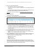
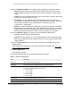
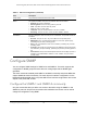


Table Of Contents
- 24-Port Gigabit (Hi-Power) PoE+ Ethernet Smart Managed Pro Switch with 2 SFP Ports and Cloud Management
- Contents
- 1 Get Started
- Available publications
- Switch management options and default management mode
- Manage the switch by using the local browser UI
- About on-network and off-network access
- Access the switch on-network and connected to the Internet
- Use a Windows-based computer to access the switch on-network
- Use the NETGEAR Insight mobile app to discover the IP address of the switch
- Use the NETGEAR Switch Discovery Tool to discover the switch
- Discover the switch in a network with a DHCP server using the Smart Control Center
- Discover the switch in a network without a DHCP server using the Smart Control Center
- Use other options to discover the switch IP address
- Access the switch on-network when you know the switch IP address
- Access the switch off-network
- Credentials for the local browser UI
- Register the switch
- Change the language of the local browser UI
- Change the management mode of the switch
- Use the Device View of the local browser UI
- Configure interface settings
- Access the NETGEAR support website
- Access the user manual online
- 2 Configure System Information
- View or define switch system information
- Configure the switch IP address settings
- Configure the IPv6 network interface
- Configure the time settings
- Configure Denial of Service settings
- Configure the DNS settings
- Configure Green Ethernet settings
- Use the Device View
- Configure Power over Ethernet
- Configure SNMP
- Configure LLDP
- Configure DHCP snooping
- Set up PoE timer schedules
- 3 Configure Switching
- Configure the port settings and maximum frame size
- Configure link aggregation groups
- Configure VLANs
- Configure a voice VLAN
- Configure Auto-VoIP
- Configure Spanning Tree Protocol
- Configure multicast
- Manage IGMP snooping
- Configure IGMP snooping
- Configure IGMP snooping for interfaces
- View, search, or clear the IGMP snooping table
- Configure IGMP snooping for VLANs
- Modify IGMP snooping settings for a VLAN
- Disable IGMP snooping on a VLAN
- Configure one or more IGMP multicast router interfaces
- Configure an IGMP multicast router VLAN
- IGMP snooping querier overview
- Configure an IGMP snooping querier
- Configure an IGMP snooping querier for a VLAN
- Display the status of the IGMP snooping querier for VLANs
- View, search, and manage the MAC address table
- Configure Layer 2 loop protection
- 4 Configure Quality of Service
- 5 Manage Device Security
- Change the local device password for the local browser UI
- Manage the RADIUS settings
- Configure the TACACS+ settings
- Manage the Smart Control Center Utility
- Configure management access
- Control access with profiles and rules
- Configure port authentication
- Set up traffic control
- Configure access control lists
- Use the ACL Wizard to create a simple ACL
- Configure a MAC ACL
- Configure MAC ACL rules
- Configure MAC bindings
- View or delete MAC ACL bindings in the MAC binding table
- Configure a basic or extended IPv4 ACL
- Configure rules for a basic IPv4 ACL
- Configure rules for an extended IPv4 ACL
- Configure an IPv6 ACL
- Configure rules for an IPv6 ACL
- Configure IP ACL interface bindings
- View or delete IP ACL bindings in the IP ACL binding table
- Configure VLAN ACL bindings
- 6 Monitor the System
- 7 Maintain or Troubleshoot the Switch
- A Configuration Examples
- B Specifications and Default Settings

24-Port Gigabit (Hi-Power) PoE+ Ethernet Smart Managed Pro Switch with 2 SFP Ports
Configure System Information User Manual95
10. From the High Power Mode menu, select the PoE mode that the port must function in:
• 802.3af. The port is powered in and limited to the IEEE 802.3af mode.
A PD that
requires IEEE 802.3at does not receive power if the port functions in IEEE 802.3af
mode.
• Legacy. The port is powered using high-inrush current, which is used
by legacy PDs
that require more than 15W to power up.
• Pre-802.3at. The port is initially powered in the IEEE 802.3af mode and, b
efore
75 msec pass, is switched to the high-power IEEE 802.3at mode. Select this mode if
the PD does not perform Layer 2 classification or if the switch performs
2-event Layer 1 classification.
• 802.3at. The port is powered in the IEEE 802.3at mode and is backward
compatible
with IEEE 802.3af. The 802.3at mode is the default mode. In this mode, if the switch
detects that the attached PD requests more power than IEEE 802.3af but is not an
IEEE 802.3at Class 4 device, the PD does not receive power from the switch.
11. From the Detection
Type menu, select how the port detects the attached PD:
• pre-ieee. The port performs legacy detection.
•
ieee auto. The port performs a 4-point resistive detection.
This is the default setting.
• auto. The port performs a 4-point resistive detection, and if required, continues with
legacy detection.
12. From the T
imer Schedule menu, select a timer schedule or select None, which is the
default selection.
For information about setting up and configuring PoE timer schedules, see
Set up PoE
timer schedules on page 125.
13. Click the Apply
button.
Your settings are saved.
The following table describes the nonconfigurable fields on the page.
Table 17. PoE Port Configuration
Field Description
High Power All ports supports high-power mode.
Max Power The maximum power in milliwatts that can be provided by the port.
Class The class defines the range of power that a powered device (PD) is drawing from
the switch.
The class definitions are as follows:
•
0:
0.44–12.95W
•
1: 0.44–3.83W
• 2: 0.44–6.48W
• 3: 0.44–12.95W
• 4: 0.44–25.5W
Output Voltage The voltage that is delivered to the PD in volts.
Output Current The current that is delivered to the PD in mA.