
User Manual
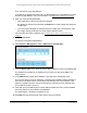
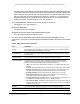

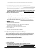
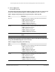

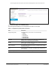
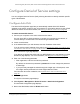

Table Of Contents
- 24-Port Gigabit (Hi-Power) PoE+ Ethernet Smart Managed Pro Switch with 2 SFP Ports and Cloud Management
- Contents
- 1 Get Started
- Available publications
- Switch management options and default management mode
- Manage the switch by using the local browser UI
- About on-network and off-network access
- Access the switch on-network and connected to the Internet
- Use a Windows-based computer to access the switch on-network
- Use the NETGEAR Insight mobile app to discover the IP address of the switch
- Use the NETGEAR Switch Discovery Tool to discover the switch
- Discover the switch in a network with a DHCP server using the Smart Control Center
- Discover the switch in a network without a DHCP server using the Smart Control Center
- Use other options to discover the switch IP address
- Access the switch on-network when you know the switch IP address
- Access the switch off-network
- Credentials for the local browser UI
- Register the switch
- Change the language of the local browser UI
- Change the management mode of the switch
- Use the Device View of the local browser UI
- Configure interface settings
- Access the NETGEAR support website
- Access the user manual online
- 2 Configure System Information
- View or define switch system information
- Configure the switch IP address settings
- Configure the IPv6 network interface
- Configure the time settings
- Configure Denial of Service settings
- Configure the DNS settings
- Configure Green Ethernet settings
- Use the Device View
- Configure Power over Ethernet
- Configure SNMP
- Configure LLDP
- Configure DHCP snooping
- Set up PoE timer schedules
- 3 Configure Switching
- Configure the port settings and maximum frame size
- Configure link aggregation groups
- Configure VLANs
- Configure a voice VLAN
- Configure Auto-VoIP
- Configure Spanning Tree Protocol
- Configure multicast
- Manage IGMP snooping
- Configure IGMP snooping
- Configure IGMP snooping for interfaces
- View, search, or clear the IGMP snooping table
- Configure IGMP snooping for VLANs
- Modify IGMP snooping settings for a VLAN
- Disable IGMP snooping on a VLAN
- Configure one or more IGMP multicast router interfaces
- Configure an IGMP multicast router VLAN
- IGMP snooping querier overview
- Configure an IGMP snooping querier
- Configure an IGMP snooping querier for a VLAN
- Display the status of the IGMP snooping querier for VLANs
- View, search, and manage the MAC address table
- Configure Layer 2 loop protection
- 4 Configure Quality of Service
- 5 Manage Device Security
- Change the local device password for the local browser UI
- Manage the RADIUS settings
- Configure the TACACS+ settings
- Manage the Smart Control Center Utility
- Configure management access
- Control access with profiles and rules
- Configure port authentication
- Set up traffic control
- Configure access control lists
- Use the ACL Wizard to create a simple ACL
- Configure a MAC ACL
- Configure MAC ACL rules
- Configure MAC bindings
- View or delete MAC ACL bindings in the MAC binding table
- Configure a basic or extended IPv4 ACL
- Configure rules for a basic IPv4 ACL
- Configure rules for an extended IPv4 ACL
- Configure an IPv6 ACL
- Configure rules for an IPv6 ACL
- Configure IP ACL interface bindings
- View or delete IP ACL bindings in the IP ACL binding table
- Configure VLAN ACL bindings
- 6 Monitor the System
- 7 Maintain or Troubleshoot the Switch
- A Configuration Examples
- B Specifications and Default Settings

24-Port Gigabit (Hi-Power) PoE+ Ethernet Smart Managed Pro Switch with 2 SFP Ports
Configure System Information User Manual72
The SNTP client on the device continues sending SNTP requests to different servers until
a successful response is received, or all servers are exhausted. The priority indicates the
order in which to query the servers. The request is sent to an SNTP server with a priority
value of 1 first, then to a server with a priority value of 2, and so on. If any servers are
assigned the same priority, the SNTP client contacts the servers in the order that they
appear in the table. The valid range is 1 to 3. The default is 1.
11. In
the Version field, specify the NTP version running on the server.
The range is 1 to 4.
The default is 4.
12. Click the Add
button.
The SNTP server entry is added.
13. Repeat the previous
steps to add additional SNTP servers.
You can configure up to three SNTP servers.
The SNTP Server Status table displays status information about the SNTP servers
configured on your
switch. The following table describes the fields in the SNTP Server Status
table.
Table 8. SNTP Server Status information
Field Description
Address All the existing server addresses. If no server configuration exists, a message stating
that no SNTP server exists displays on the page.
Last Update Time The local date and time (UTC) that the response from this server was used to update
the system clock.
Last Attempt Time The local date and time (UTC) that this SNTP server was last queried.
Last Attempt Status The status of the last SNTP request or unsolicited message for both unicast and
broadcast modes. If no message was received from a server
, a status of Other is
displayed.
These values are appropriate for all operational modes:
Requests The number of SNTP requests made to this server since last agent reboot.
Failed Requests The number of failed SNTP requests made to this server since the last reboot.
• Other. The status of the last request is unknown, or no SNTP responses were
received.
• Success
. The SNTP operation was successful and the system time was updated.
• Request Timed Out. After an SNTP request was sent to an SNTP server, the
response timer expired before a response from the server was received.
• Bad Date Encoded. The time provided by the SNTP server is not valid.
• Version Not Supported. The SNTP version supported by the server is not
compatible with the version supported by the client.
• Server Unsynchronized. The SNTP server is not synchronized with its peers. This
is indicated by the leap indicator field on the SNTP message.
• Server Kiss Of Death. The SNTP server indicated that no further queries were to
be sent to this server. This is indicated by a stratum field equal to 0 in a message
received from a server.