
User Manual


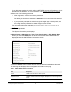
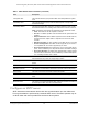

Table Of Contents
- 24-Port Gigabit (Hi-Power) PoE+ Ethernet Smart Managed Pro Switch with 2 SFP Ports and Cloud Management
- Contents
- 1 Get Started
- Available publications
- Switch management options and default management mode
- Manage the switch by using the local browser UI
- About on-network and off-network access
- Access the switch on-network and connected to the Internet
- Use a Windows-based computer to access the switch on-network
- Use the NETGEAR Insight mobile app to discover the IP address of the switch
- Use the NETGEAR Switch Discovery Tool to discover the switch
- Discover the switch in a network with a DHCP server using the Smart Control Center
- Discover the switch in a network without a DHCP server using the Smart Control Center
- Use other options to discover the switch IP address
- Access the switch on-network when you know the switch IP address
- Access the switch off-network
- Credentials for the local browser UI
- Register the switch
- Change the language of the local browser UI
- Change the management mode of the switch
- Use the Device View of the local browser UI
- Configure interface settings
- Access the NETGEAR support website
- Access the user manual online
- 2 Configure System Information
- View or define switch system information
- Configure the switch IP address settings
- Configure the IPv6 network interface
- Configure the time settings
- Configure Denial of Service settings
- Configure the DNS settings
- Configure Green Ethernet settings
- Use the Device View
- Configure Power over Ethernet
- Configure SNMP
- Configure LLDP
- Configure DHCP snooping
- Set up PoE timer schedules
- 3 Configure Switching
- Configure the port settings and maximum frame size
- Configure link aggregation groups
- Configure VLANs
- Configure a voice VLAN
- Configure Auto-VoIP
- Configure Spanning Tree Protocol
- Configure multicast
- Manage IGMP snooping
- Configure IGMP snooping
- Configure IGMP snooping for interfaces
- View, search, or clear the IGMP snooping table
- Configure IGMP snooping for VLANs
- Modify IGMP snooping settings for a VLAN
- Disable IGMP snooping on a VLAN
- Configure one or more IGMP multicast router interfaces
- Configure an IGMP multicast router VLAN
- IGMP snooping querier overview
- Configure an IGMP snooping querier
- Configure an IGMP snooping querier for a VLAN
- Display the status of the IGMP snooping querier for VLANs
- View, search, and manage the MAC address table
- Configure Layer 2 loop protection
- 4 Configure Quality of Service
- 5 Manage Device Security
- Change the local device password for the local browser UI
- Manage the RADIUS settings
- Configure the TACACS+ settings
- Manage the Smart Control Center Utility
- Configure management access
- Control access with profiles and rules
- Configure port authentication
- Set up traffic control
- Configure access control lists
- Use the ACL Wizard to create a simple ACL
- Configure a MAC ACL
- Configure MAC ACL rules
- Configure MAC bindings
- View or delete MAC ACL bindings in the MAC binding table
- Configure a basic or extended IPv4 ACL
- Configure rules for a basic IPv4 ACL
- Configure rules for an extended IPv4 ACL
- Configure an IPv6 ACL
- Configure rules for an IPv6 ACL
- Configure IP ACL interface bindings
- View or delete IP ACL bindings in the IP ACL binding table
- Configure VLAN ACL bindings
- 6 Monitor the System
- 7 Maintain or Troubleshoot the Switch
- A Configuration Examples
- B Specifications and Default Settings

24-Port Gigabit (Hi-Power) PoE+ Ethernet Smart Managed Pro Switch with 2 SFP Ports
Configure System Information User Manual64
determine the time and, optionally, the round-trip delay and local clock offset relative
to the server.
• Broadcast. SNTP operates in the same manner as multicast mode but uses a local
broadcast address instead of a multicast address. The broadcast address provides a
single-subnet scope while a multicast address provides an Inter
net-wide scope.
The default is Disable.
9. If the SNTP client mode is Unicast, you can add the IP address or DNS name of one or
more SNTP servers for the switch to poll.
For more information, see
Configure an SNTP server on page 69.
10. In the Port
field, specify the local UDP port that the SNTP client receives server packets on.
The allowed range is 1025 to 65535 and 123. The default is 123. When the default is
configured, the actual client port value used in SNTP packets is assigned by the OS.
11. In the Unicast
Poll Interval field, specify the number of seconds between unicast poll
requests expressed as a power of 2. to The allowed range is 6 to 10. The default is 6.
12. In the Broadcast
Poll Interval field, specify the number of seconds between broadcast poll
requests expressed as a power of 2.
Broadcasts received prior to the expiry of this interval are discarded. The
allowed range is
6 to 10. The default is 6.
13. In the Unicast Poll Timeout field, specify the number of seconds to wait for an SNTP
response to a unicast poll request.
The allowed range is 1 to 30. The default is 5.
14. In the Unicast
Poll Retry field, specify the number of times to retry a unicast poll request to
an SNTP server after the first time-out before the switch attempts to use the next configured
server.
The allowed range is 0 to 10. The default is 1.
15. In the T
ime Zone Name field, specify a time zone.
You can also specify the number of hours and number of minutes that the time zone is
different from the Coordinated Universal Time (UTC).
The time zone can affect the
display of the current system time. The default is UTC.
Note: When
using
SNTP/NTP time servers to update the switch’s clock, the
time data received from the server is based on the UTC, which is the
same as Greenwich Mean Time (GMT). This might not be the time
zone in which the switch is located.
16. In
the Offset
Hours field, specify the number of hours that the time zone is different from
UTC.
The allowed range is –12 to 13. The default is 0.
17. In the Offset
Minutes field, specify the number of minutes that the time zone is different
from UTC.