
User Manual
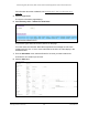


Table Of Contents
- 24-Port Gigabit (Hi-Power) PoE+ Ethernet Smart Managed Pro Switch with 2 SFP Ports and Cloud Management
- Contents
- 1 Get Started
- Available publications
- Switch management options and default management mode
- Manage the switch by using the local browser UI
- About on-network and off-network access
- Access the switch on-network and connected to the Internet
- Use a Windows-based computer to access the switch on-network
- Use the NETGEAR Insight mobile app to discover the IP address of the switch
- Use the NETGEAR Switch Discovery Tool to discover the switch
- Discover the switch in a network with a DHCP server using the Smart Control Center
- Discover the switch in a network without a DHCP server using the Smart Control Center
- Use other options to discover the switch IP address
- Access the switch on-network when you know the switch IP address
- Access the switch off-network
- Credentials for the local browser UI
- Register the switch
- Change the language of the local browser UI
- Change the management mode of the switch
- Use the Device View of the local browser UI
- Configure interface settings
- Access the NETGEAR support website
- Access the user manual online
- 2 Configure System Information
- View or define switch system information
- Configure the switch IP address settings
- Configure the IPv6 network interface
- Configure the time settings
- Configure Denial of Service settings
- Configure the DNS settings
- Configure Green Ethernet settings
- Use the Device View
- Configure Power over Ethernet
- Configure SNMP
- Configure LLDP
- Configure DHCP snooping
- Set up PoE timer schedules
- 3 Configure Switching
- Configure the port settings and maximum frame size
- Configure link aggregation groups
- Configure VLANs
- Configure a voice VLAN
- Configure Auto-VoIP
- Configure Spanning Tree Protocol
- Configure multicast
- Manage IGMP snooping
- Configure IGMP snooping
- Configure IGMP snooping for interfaces
- View, search, or clear the IGMP snooping table
- Configure IGMP snooping for VLANs
- Modify IGMP snooping settings for a VLAN
- Disable IGMP snooping on a VLAN
- Configure one or more IGMP multicast router interfaces
- Configure an IGMP multicast router VLAN
- IGMP snooping querier overview
- Configure an IGMP snooping querier
- Configure an IGMP snooping querier for a VLAN
- Display the status of the IGMP snooping querier for VLANs
- View, search, and manage the MAC address table
- Configure Layer 2 loop protection
- 4 Configure Quality of Service
- 5 Manage Device Security
- Change the local device password for the local browser UI
- Manage the RADIUS settings
- Configure the TACACS+ settings
- Manage the Smart Control Center Utility
- Configure management access
- Control access with profiles and rules
- Configure port authentication
- Set up traffic control
- Configure access control lists
- Use the ACL Wizard to create a simple ACL
- Configure a MAC ACL
- Configure MAC ACL rules
- Configure MAC bindings
- View or delete MAC ACL bindings in the MAC binding table
- Configure a basic or extended IPv4 ACL
- Configure rules for a basic IPv4 ACL
- Configure rules for an extended IPv4 ACL
- Configure an IPv6 ACL
- Configure rules for an IPv6 ACL
- Configure IP ACL interface bindings
- View or delete IP ACL bindings in the IP ACL binding table
- Configure VLAN ACL bindings
- 6 Monitor the System
- 7 Maintain or Troubleshoot the Switch
- A Configuration Examples
- B Specifications and Default Settings

24-Port Gigabit (Hi-Power) PoE+ Ethernet Smart Managed Pro Switch with 2 SFP Ports
Manage Device Security User Manual342
9. Configure the following match criteria for the rule:
• Action. Select the ACL forwarding action by selecting one of the foll
owing radio
buttons:
- Permit. Forward packets that meet the ACL criteria.
-
Deny. Drop packets that meet the ACL criteria.
•
Egress Queue. If you select the Permit radio button, select the hardware egress
queue identifier that is used to handle all packets matching this IPv6 ACL rule.
The
range of queue IDs is 0 to 7.
• Logging. If you select the Deny radio button, you can enable logging for the ACL by
selecting the
Enable radio button. (Logging is subject to resource availability in the
device.)
If the access list trap flag is also enabled, periodic traps are generated,
indicating the
number of times this rule was evoked during the report interval. A fixed five-minute
report interval is used for the switch. A trap is not issued if the ACL rule hit count is
zero for the current interval.
• Interface. For a Permit action, use either a mirror interface or a redirect interface:
- Select the Mirror radio
button and use the menu to specify the egress interface to
which the matching traffic stream is copied, in addition to being forwarded
normally by the device.
- Select the Redirect radio
button and use the menu to specify the egress interface
to which the matching traffic stream is forced, bypassing any forwarding decision
normally performed by the device.
• Match Every. Select whether all packet must match the selected IPv6 ACL ru
le:
- False. Not all packets need to match the selected IPv6 ACL rule.
You can
configure other match criteria on the page.
- True. All packets must match the selected IPv6 ACL rule and are either permitted
or denied. In this case, you cannot configure other match crite
ria on the page.
• Protocol Type. Specify the IPv6 protocol type in one of the following ways:
- From the Protocol T
ype menu, select
IPv6, ICMPv6, TCP, or UDP.
- From the Protocol Type menu, select
Other, and in the associated field, specify
an integer ranging from 0 to 255. This number represents the IPv6 protocol.
• Src. In the Src
field, enter a source IPv6 address or source IPv6 address range to be
compared to a packet’s source IPv6 address as a match criterion for the selected
IPv6 ACL rule:
- If you select the IPv6 Address
radio button, enter an IPv6 address or IPv6 range
to apply this criteria. If this field is left empty, it means any.
- If you select the Host
radio button, enter a host source IPv6 address to match the
specified IPv6 address. If this field is left empty, it means any.
The source IPv6 address argument must be in the form documented in RFC 2373
where the address is specified in hexadecimal numbers using 16-bit values between
colons.