
User Manual

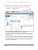


Table Of Contents
- 24-Port Gigabit (Hi-Power) PoE+ Ethernet Smart Managed Pro Switch with 2 SFP Ports and Cloud Management
- Contents
- 1 Get Started
- Available publications
- Switch management options and default management mode
- Manage the switch by using the local browser UI
- About on-network and off-network access
- Access the switch on-network and connected to the Internet
- Use a Windows-based computer to access the switch on-network
- Use the NETGEAR Insight mobile app to discover the IP address of the switch
- Use the NETGEAR Switch Discovery Tool to discover the switch
- Discover the switch in a network with a DHCP server using the Smart Control Center
- Discover the switch in a network without a DHCP server using the Smart Control Center
- Use other options to discover the switch IP address
- Access the switch on-network when you know the switch IP address
- Access the switch off-network
- Credentials for the local browser UI
- Register the switch
- Change the language of the local browser UI
- Change the management mode of the switch
- Use the Device View of the local browser UI
- Configure interface settings
- Access the NETGEAR support website
- Access the user manual online
- 2 Configure System Information
- View or define switch system information
- Configure the switch IP address settings
- Configure the IPv6 network interface
- Configure the time settings
- Configure Denial of Service settings
- Configure the DNS settings
- Configure Green Ethernet settings
- Use the Device View
- Configure Power over Ethernet
- Configure SNMP
- Configure LLDP
- Configure DHCP snooping
- Set up PoE timer schedules
- 3 Configure Switching
- Configure the port settings and maximum frame size
- Configure link aggregation groups
- Configure VLANs
- Configure a voice VLAN
- Configure Auto-VoIP
- Configure Spanning Tree Protocol
- Configure multicast
- Manage IGMP snooping
- Configure IGMP snooping
- Configure IGMP snooping for interfaces
- View, search, or clear the IGMP snooping table
- Configure IGMP snooping for VLANs
- Modify IGMP snooping settings for a VLAN
- Disable IGMP snooping on a VLAN
- Configure one or more IGMP multicast router interfaces
- Configure an IGMP multicast router VLAN
- IGMP snooping querier overview
- Configure an IGMP snooping querier
- Configure an IGMP snooping querier for a VLAN
- Display the status of the IGMP snooping querier for VLANs
- View, search, and manage the MAC address table
- Configure Layer 2 loop protection
- 4 Configure Quality of Service
- 5 Manage Device Security
- Change the local device password for the local browser UI
- Manage the RADIUS settings
- Configure the TACACS+ settings
- Manage the Smart Control Center Utility
- Configure management access
- Control access with profiles and rules
- Configure port authentication
- Set up traffic control
- Configure access control lists
- Use the ACL Wizard to create a simple ACL
- Configure a MAC ACL
- Configure MAC ACL rules
- Configure MAC bindings
- View or delete MAC ACL bindings in the MAC binding table
- Configure a basic or extended IPv4 ACL
- Configure rules for a basic IPv4 ACL
- Configure rules for an extended IPv4 ACL
- Configure an IPv6 ACL
- Configure rules for an IPv6 ACL
- Configure IP ACL interface bindings
- View or delete IP ACL bindings in the IP ACL binding table
- Configure VLAN ACL bindings
- 6 Monitor the System
- 7 Maintain or Troubleshoot the Switch
- A Configuration Examples
- B Specifications and Default Settings

24-Port Gigabit (Hi-Power) PoE+ Ethernet Smart Managed Pro Switch with 2 SFP Ports
Get Started User Manual17
User-defined fields
User-defined fields can contain 1 to 159 characters, unless otherwise noted on the
configuration web page. All characters can be used except for the ones stated in the
following table (unless specifically noted in a procedure for a feature).
Table 2. Invalid characters for user-defined fields
Invalid characters for user-defined fields
\ | / < > * ?
Context-sensitive help
When you log in to the switch, every page contains a link to the online help () that contains
information to assist in configuring and managing the switch. The online help pages are
context sensitive. For example, if the IP Configuration page is open, the help topic for that
page displays if you click the link to the online help.
About on-network and off-network access
You can access the switch either on-network or off-network:
• On-network and connected to the Internet. When you use the local browser UI, for
easiest access, we recommend that you cable the switch to a network that is connected
to the Internet and that includes a router or DHCP server that assigns IP addresses,
power on the switch, and then use a computer that is connected to the same network as
the switch to connect to the local browser UI. W
e refer to this setup as on-network or
online.
For more information, see
Access the switch on-network and connected to the Internet
on page 18).
• Off-network and not connected to the Internet. You can also configure the switch
connected directly only to the computer that you are using to c
onfigure it. That is, the
switch is not connected to the network and the Internet. We refer to this setup as
off-network or offline.
Before you can access the full menu of the local browser UI, you must connect the switch to
a network with Internet access at least once so that you can register the switch with
NETGEAR and unlock the full menu. Alternately, you can get a re
gistration key, which you
can enter to unlock the full menu while the switch is off-network.
For more information, see the following sections:
•
Register the switch on page 31.
•
Access the switch off-network on page 27.