
User Manual

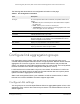

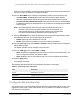


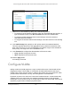
Table Of Contents
- 24-Port Gigabit (Hi-Power) PoE+ Ethernet Smart Managed Pro Switch with 2 SFP Ports and Cloud Management
- Contents
- 1 Get Started
- Available publications
- Switch management options and default management mode
- Manage the switch by using the local browser UI
- About on-network and off-network access
- Access the switch on-network and connected to the Internet
- Use a Windows-based computer to access the switch on-network
- Use the NETGEAR Insight mobile app to discover the IP address of the switch
- Use the NETGEAR Switch Discovery Tool to discover the switch
- Discover the switch in a network with a DHCP server using the Smart Control Center
- Discover the switch in a network without a DHCP server using the Smart Control Center
- Use other options to discover the switch IP address
- Access the switch on-network when you know the switch IP address
- Access the switch off-network
- Credentials for the local browser UI
- Register the switch
- Change the language of the local browser UI
- Change the management mode of the switch
- Use the Device View of the local browser UI
- Configure interface settings
- Access the NETGEAR support website
- Access the user manual online
- 2 Configure System Information
- View or define switch system information
- Configure the switch IP address settings
- Configure the IPv6 network interface
- Configure the time settings
- Configure Denial of Service settings
- Configure the DNS settings
- Configure Green Ethernet settings
- Use the Device View
- Configure Power over Ethernet
- Configure SNMP
- Configure LLDP
- Configure DHCP snooping
- Set up PoE timer schedules
- 3 Configure Switching
- Configure the port settings and maximum frame size
- Configure link aggregation groups
- Configure VLANs
- Configure a voice VLAN
- Configure Auto-VoIP
- Configure Spanning Tree Protocol
- Configure multicast
- Manage IGMP snooping
- Configure IGMP snooping
- Configure IGMP snooping for interfaces
- View, search, or clear the IGMP snooping table
- Configure IGMP snooping for VLANs
- Modify IGMP snooping settings for a VLAN
- Disable IGMP snooping on a VLAN
- Configure one or more IGMP multicast router interfaces
- Configure an IGMP multicast router VLAN
- IGMP snooping querier overview
- Configure an IGMP snooping querier
- Configure an IGMP snooping querier for a VLAN
- Display the status of the IGMP snooping querier for VLANs
- View, search, and manage the MAC address table
- Configure Layer 2 loop protection
- 4 Configure Quality of Service
- 5 Manage Device Security
- Change the local device password for the local browser UI
- Manage the RADIUS settings
- Configure the TACACS+ settings
- Manage the Smart Control Center Utility
- Configure management access
- Control access with profiles and rules
- Configure port authentication
- Set up traffic control
- Configure access control lists
- Use the ACL Wizard to create a simple ACL
- Configure a MAC ACL
- Configure MAC ACL rules
- Configure MAC bindings
- View or delete MAC ACL bindings in the MAC binding table
- Configure a basic or extended IPv4 ACL
- Configure rules for a basic IPv4 ACL
- Configure rules for an extended IPv4 ACL
- Configure an IPv6 ACL
- Configure rules for an IPv6 ACL
- Configure IP ACL interface bindings
- View or delete IP ACL bindings in the IP ACL binding table
- Configure VLAN ACL bindings
- 6 Monitor the System
- 7 Maintain or Troubleshoot the Switch
- A Configuration Examples
- B Specifications and Default Settings

24-Port Gigabit (Hi-Power) PoE+ Ethernet Smart Managed Pro Switch with 2 SFP Ports
Configure Switching User Manual134
The following table describes the nonconfigurable information on the page.
Table 21. Port Configuration information
Field Description
Port Type For normal ports this field is blank. Otherwise, the possible values are as
follows:
Physical Status Indicates the port speed and duplex mode.
Link Status Indicates whether the link is up or down.
Frame Size (1522 to 10000) The maximum Ethernet frame size that each interface can support.
The
frame size depends on your selection from the Frame Size
menu above
the table and applies to each interface.
MAC Address Displays the physical address of the specified interface.
PortList Bit Offset Displays the bit offset value that corresponds to the port when the MIB
object type PortList is used to manage in SNMP
.
ifIndex The ifIndex of the interface table entry associated with this port.
Configure link aggregation groups
Link aggregation groups (LAGs), which are also known as port channels, allow you to
combine multiple full-duplex Ethernet links into a single logical link. Network devices treat the
aggregation as if it were a single link, which increases fault tolerance and provides load
sharing. You assign the LAG VLAN membership after you create a LAG. The LAG by default
becomes a member of the default management VLAN (that is, VLAN 1).
A LAG interface can be either static or dynamic, but not both. All members of a LAG must
participate in the same protocols.
A static port channel interface does not require a partner
system to be able to aggregate its member ports.
Static LAGs are supported. When a port is added to a LAG as a s
tatic member, it neither
transmits nor receives LACPDUs. The switch supports eight LAGs.
Configure LAG settings
You can group one or more full-duplex Ethernet links to be aggregated together to form a link
aggregation group, which is also known as a port channel. The switch treats the LAG as if it
were a single link.
• Mirrored. The port is a mirrored port on which all the traffic is copied to
the probe port.
• Probe. Use this port to monitor a mirrored port.
• Trunk Member. The port is a member of a link aggregation trunk. Look
at the LAG pages for more information.