
User Manual


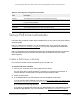
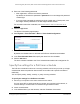


Table Of Contents
- 24-Port Gigabit (Hi-Power) PoE+ Ethernet Smart Managed Pro Switch with 2 SFP Ports and Cloud Management
- Contents
- 1 Get Started
- Available publications
- Switch management options and default management mode
- Manage the switch by using the local browser UI
- About on-network and off-network access
- Access the switch on-network and connected to the Internet
- Use a Windows-based computer to access the switch on-network
- Use the NETGEAR Insight mobile app to discover the IP address of the switch
- Use the NETGEAR Switch Discovery Tool to discover the switch
- Discover the switch in a network with a DHCP server using the Smart Control Center
- Discover the switch in a network without a DHCP server using the Smart Control Center
- Use other options to discover the switch IP address
- Access the switch on-network when you know the switch IP address
- Access the switch off-network
- Credentials for the local browser UI
- Register the switch
- Change the language of the local browser UI
- Change the management mode of the switch
- Use the Device View of the local browser UI
- Configure interface settings
- Access the NETGEAR support website
- Access the user manual online
- 2 Configure System Information
- View or define switch system information
- Configure the switch IP address settings
- Configure the IPv6 network interface
- Configure the time settings
- Configure Denial of Service settings
- Configure the DNS settings
- Configure Green Ethernet settings
- Use the Device View
- Configure Power over Ethernet
- Configure SNMP
- Configure LLDP
- Configure DHCP snooping
- Set up PoE timer schedules
- 3 Configure Switching
- Configure the port settings and maximum frame size
- Configure link aggregation groups
- Configure VLANs
- Configure a voice VLAN
- Configure Auto-VoIP
- Configure Spanning Tree Protocol
- Configure multicast
- Manage IGMP snooping
- Configure IGMP snooping
- Configure IGMP snooping for interfaces
- View, search, or clear the IGMP snooping table
- Configure IGMP snooping for VLANs
- Modify IGMP snooping settings for a VLAN
- Disable IGMP snooping on a VLAN
- Configure one or more IGMP multicast router interfaces
- Configure an IGMP multicast router VLAN
- IGMP snooping querier overview
- Configure an IGMP snooping querier
- Configure an IGMP snooping querier for a VLAN
- Display the status of the IGMP snooping querier for VLANs
- View, search, and manage the MAC address table
- Configure Layer 2 loop protection
- 4 Configure Quality of Service
- 5 Manage Device Security
- Change the local device password for the local browser UI
- Manage the RADIUS settings
- Configure the TACACS+ settings
- Manage the Smart Control Center Utility
- Configure management access
- Control access with profiles and rules
- Configure port authentication
- Set up traffic control
- Configure access control lists
- Use the ACL Wizard to create a simple ACL
- Configure a MAC ACL
- Configure MAC ACL rules
- Configure MAC bindings
- View or delete MAC ACL bindings in the MAC binding table
- Configure a basic or extended IPv4 ACL
- Configure rules for a basic IPv4 ACL
- Configure rules for an extended IPv4 ACL
- Configure an IPv6 ACL
- Configure rules for an IPv6 ACL
- Configure IP ACL interface bindings
- View or delete IP ACL bindings in the IP ACL binding table
- Configure VLAN ACL bindings
- 6 Monitor the System
- 7 Maintain or Troubleshoot the Switch
- A Configuration Examples
- B Specifications and Default Settings

Table 20. DHCP Dynamic Configuration information
Field Description
Interface The interface on which the DHCP client message was received.
MAC Address The MAC address associated with the DHCP client that sent the message. This is the
key to the binding database.
VLAN ID The VLAN ID of the client interface.
IP Address The IP address assigned to the client by the DHCP server
.
Lease Time The remaining IP address lease time for the client.
24-Port Gigabit (Hi-Power) PoE+ Ethernet Smart Managed Pro Switch with 2 SFP Ports
Configure System Information User Manual125
Set up PoE timer schedules
The switch lets you define multiple timer schedules that you can use for PoE power delivery
to attached PDs.
After you create a timer schedule, you can associate it with one or more PoE ports (see
Configure the PoE port settings on page 93). You can use a separate timer schedule for
each PoE port.
After you associate a timer schedule with a PoE port, the start date and time force the PoE
port to stop delivering power and the stop date and time enable the PoE port to start
delivering power.
Create a PoE timer schedule
The maximum number of timer schedules that you can add is 25.
To create a PoE timer schedule:
1. Connect your computer
to the same network as the switch.
You can use a WiFi or wired connection to connect your computer to the network, or
connect directly to a switch that is off-network using an Ethernet cable.
2. Launch
a web browser.
3. In the address field of your web browser, enter the IP address of the switch.
If you do not know the IP address of the switch, see
Access the switch on-network and
connected to the Internet on page 18 or Access the switch off-network on page 27.
The Local Device Login page displays.
If you did not yet register the switch with your NETGEAR account, the Register
to unlock
all features page displays. For more information, see
Register the switch on page 31.