
User Manual


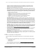
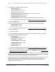


Table Of Contents
- 8-Port or 16-Port Gigabit Smart Managed Pro Switch with PoE+ and 2 SFP Ports
- Contents
- 1 Get Started
- Available publications
- Switch management and discovery overview
- Change the default IP address of the switch
- Discover or change the switch IP address
- About the user interfaces
- Access the local browser interface
- Change the language of the local browser interface
- Use the Device View of the local browser interface
- Interface naming conventions
- Configure interface settings
- Context–sensitive help and access to the support website
- Access the user manual online
- Register your product
- 2 Configure System Information
- View or define system information
- Configure the IP network settings for management access
- Configure the time settings
- Configure denial of service settings
- Configure the DNS settings
- Configure green Ethernet settings
- Use the Device View
- Configure Power over Ethernet
- Configure SNMP
- Configure LLDP
- Configure a DHCP L2 relay, DHCP snooping, and dynamic ARP inspection
- Set up PoE timer schedules
- 3 Configure Switching
- Configure the port settings
- Configure link aggregation groups
- Configure VLANs
- Configure a voice VLAN
- Configure Auto-VoIP
- Configure Spanning Tree Protocol
- Configure multicast
- Manage IGMP snooping
- Configure IGMP snooping
- Configure IGMP snooping for interfaces
- View, search, or clear the IGMP snooping table
- Configure IGMP snooping for VLANs
- Modify IGMP snooping settings for a VLAN
- Disable IGMP snooping on a VLAN and remove it from the table
- Configure one or more IGMP multicast router interfaces
- Configure an IGMP multicast router VLAN
- IGMP snooping querier overview
- Configure an IGMP snooping querier
- Configure an IGMP snooping querier for a VLAN
- Display the status of the IGMP snooping querier for VLANs
- Manage MLD snooping
- Enable MLD snooping
- Configure MLD snooping for interfaces
- Configure the MLD VLAN settings
- Modify the MLD snooping settings for a VLAN
- Remove MLD snooping from a VLAN
- Configure one or more MLD multicast router interfaces
- Configure an MLD multicast router VLAN
- Configure an MLD snooping querier
- Configure the MLD snooping querier VLAN settings
- Configure multicast VLAN registration
- View, search, and manage the MAC address table
- Configure Layer 2 loop protection
- 4 Configure Routing
- 5 Configure Quality of Service
- 6 Manage Device Security
- Change the device password for the local browser interface
- Manage the RADIUS settings
- Configure the TACACS+ settings
- Configure authentication lists
- Manage the Smart Control Center Utility
- Configure management access
- Control access with profiles and rules
- Configure port authentication
- Set up traffic control
- Configure access control lists
- Use the ACL Wizard to create a simple ACL
- Configure a MAC ACL
- Configure MAC ACL rules
- Configure MAC bindings
- View or delete MAC ACL bindings in the MAC binding table
- Configure a basic or extended IPv4 ACL
- Configure rules for a basic IPv4 ACL
- Configure rules for an extended IPv4 ACL
- Configure an IPv6 ACL
- Configure rules for an IPv6 ACL
- Configure IP ACL interface bindings
- View or delete IP ACL bindings in the IP ACL binding table
- Configure VLAN ACL bindings
- 7 Monitor the Switch and the Traffic
- 8 Maintain or Troubleshoot the Switch
- A Configuration Examples
- B Specifications and Default Settings

8-Port or 16-Port Gigabit Smart Managed Pro Switch Model GS418TPP, GS510TLP, and GS510TPP
Configuration Examples User Manual452
• Assign Queue ID. 0
• Match Every. False
• CoS. 0
• Destination MAC. 01:02:1A:BC:DE:EF
• Destination MAC Mask. 00:00:00:00:FF:FF
• EtherType. User V
alue.
•
Source MAC. 02:02:1A:BC:DE:EF
• Source MAC Mask. 00:00:00:00:FF:FF
• VLAN ID. 2
For more information about MAC ACL rules, see
Configure MAC ACL rules on
page 355.
3. On the MAC Binding Configuration page, assign the Sales_ACL to the interface Gigabit
ports 6, 7, and 8, and then click the Apply button. (See
Configure MAC bindings on
page 359.)
You can assign an optional sequence number to indicate the order of this access list
relative to other access lists if any are already assigned to this interface and direction.
4. The MAC Binding T
able displays the interface and MAC ACL binding information. (See
View or delete MAC ACL bindings in the MAC binding table on page 360.)
The ACL named Sales_ACL looks for Ethernet frames with destination and source MAC
addresses and MAC masks defined in the rule. Also, the frame must be tagged with VLAN ID
2, which is the Sales department VLAN.
The CoS value of the frame must be 0, which is the
default value for Ethernet frames. Frames that match this criteria are permitted on interfaces
6, 7, and 8 and are assigned to the hardware egress queue 0, which is the default queue. All
other traffic is explicitly denied on these interfaces. To allow additional traffic to enter these
ports, you must add a new Permit rule with the desired match criteria and bind the rule to
interfaces 6, 7, and 8.
Basic IP ACL example configuration
The following example shows how to create an IP-based ACL that prevents any IP traffic
from the Finance department from being allowed on the ports that are associated with other
departments. Traffic from the Finance department is identified by each packet’s network IP
address.
1. On the IP ACL page, create a new IP
ACL with an IP ACL ID of 1. (See Configure a
basic or extended IPv4 ACL on page 361.)
2. On the IP Rules page, create a rule for IP ACL 1 with the following settings:
•
Sequence Number. 1
• Action. Deny
• Assign Queue ID. 0 (optional: 0 is the default value)
• Match Every. False