
User Manual


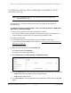


Table Of Contents
- 8-Port or 16-Port Gigabit Smart Managed Pro Switch with PoE+ and 2 SFP Ports
- Contents
- 1 Get Started
- Available publications
- Switch management and discovery overview
- Change the default IP address of the switch
- Discover or change the switch IP address
- About the user interfaces
- Access the local browser interface
- Change the language of the local browser interface
- Use the Device View of the local browser interface
- Interface naming conventions
- Configure interface settings
- Context–sensitive help and access to the support website
- Access the user manual online
- Register your product
- 2 Configure System Information
- View or define system information
- Configure the IP network settings for management access
- Configure the time settings
- Configure denial of service settings
- Configure the DNS settings
- Configure green Ethernet settings
- Use the Device View
- Configure Power over Ethernet
- Configure SNMP
- Configure LLDP
- Configure a DHCP L2 relay, DHCP snooping, and dynamic ARP inspection
- Set up PoE timer schedules
- 3 Configure Switching
- Configure the port settings
- Configure link aggregation groups
- Configure VLANs
- Configure a voice VLAN
- Configure Auto-VoIP
- Configure Spanning Tree Protocol
- Configure multicast
- Manage IGMP snooping
- Configure IGMP snooping
- Configure IGMP snooping for interfaces
- View, search, or clear the IGMP snooping table
- Configure IGMP snooping for VLANs
- Modify IGMP snooping settings for a VLAN
- Disable IGMP snooping on a VLAN and remove it from the table
- Configure one or more IGMP multicast router interfaces
- Configure an IGMP multicast router VLAN
- IGMP snooping querier overview
- Configure an IGMP snooping querier
- Configure an IGMP snooping querier for a VLAN
- Display the status of the IGMP snooping querier for VLANs
- Manage MLD snooping
- Enable MLD snooping
- Configure MLD snooping for interfaces
- Configure the MLD VLAN settings
- Modify the MLD snooping settings for a VLAN
- Remove MLD snooping from a VLAN
- Configure one or more MLD multicast router interfaces
- Configure an MLD multicast router VLAN
- Configure an MLD snooping querier
- Configure the MLD snooping querier VLAN settings
- Configure multicast VLAN registration
- View, search, and manage the MAC address table
- Configure Layer 2 loop protection
- 4 Configure Routing
- 5 Configure Quality of Service
- 6 Manage Device Security
- Change the device password for the local browser interface
- Manage the RADIUS settings
- Configure the TACACS+ settings
- Configure authentication lists
- Manage the Smart Control Center Utility
- Configure management access
- Control access with profiles and rules
- Configure port authentication
- Set up traffic control
- Configure access control lists
- Use the ACL Wizard to create a simple ACL
- Configure a MAC ACL
- Configure MAC ACL rules
- Configure MAC bindings
- View or delete MAC ACL bindings in the MAC binding table
- Configure a basic or extended IPv4 ACL
- Configure rules for a basic IPv4 ACL
- Configure rules for an extended IPv4 ACL
- Configure an IPv6 ACL
- Configure rules for an IPv6 ACL
- Configure IP ACL interface bindings
- View or delete IP ACL bindings in the IP ACL binding table
- Configure VLAN ACL bindings
- 7 Monitor the Switch and the Traffic
- 8 Maintain or Troubleshoot the Switch
- A Configuration Examples
- B Specifications and Default Settings

8-Port or 16-Port Gigabit Smart Managed Pro Switch Model GS418TPP, GS510TLP, and GS510TPP
Configuration Examples User Manual450
• Packets leaving the switch are either tagged or untagged, depending on the setting for
that port’s VLAN membership properties. A U for a given port means that packets leaving
the switch from that port are untagged. Inversely, a T for a given port means that packets
leaving the switch from that port are tagged with the VLAN ID that is associated with the
port.
The example given in this section comprises numerous steps to illustrate a wide range of
configurations to help provide an understanding of tagged VLANs.
VLAN configuration examples
This example demonstrates several scenarios of VLAN use and describes how the switch
handles tagged and untagged traffic.
In this example, you create two new VLANs, change the port membership for default VLAN 1,
and assign port members to the two new VLANs:
1. On the Basic VLAN Configuration page (see Configure VLANs on page 139), create the
following VLANs:
• A VLAN with VLAN ID 10.
• A VLAN with VLAN ID 20.
2. On the VLAN Membership page (see
Configure VLAN membership on page 142) specify
the VLAN membership as follows:
• For the default VLAN with VLAN ID 1, specify the following members: port 7 (U) and
port 8 (U).
• For the VLAN with VLAN ID 10, specify the following members: port 1 (U), port 2 (U),
and port 3 (T).
• For the VLAN with VLAN ID 20, specify the following members: port 4 (U), port 5 (T),
and port 6 (U).
3. On the Port PVID Configuration page (see
Configure the port PVID settings on
page 145), specify the PVID for ports g1 and g4 so that packets entering these ports are
tagged with the port VLAN ID:
• Port g1: PVID 10
• Port g4: PVID 20
4. With the VLAN configuration that you set up, the following situations produce results as
described:
• If an untagged packet enters port 1, the switch tags it with VLAN ID 10. The packet
can access port 2 and port 3.
The outgoing packet is stripped of its tag to leave port 2
as an untagged packet. For port 3, the outgoing packet leaves as a tagged packet
with VLAN ID 10.
• If a tagged packet with VLAN ID 10 enters port 3, the packet can access port 1 and
port 2. If the packet leaves port 1 or port 2, it is stripped of its tag to leave the switch
as an untagged packet.
• If an untagged packet enters port 4, the switch tags it with VLAN ID 20. The packet
can access port 5 and port 6. The outgoing packet is stripped of its tag to become an