
User Manual

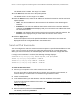

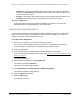
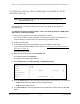


Table Of Contents
- 8-Port or 16-Port Gigabit Smart Managed Pro Switch with PoE+ and 2 SFP Ports
- Contents
- 1 Get Started
- Available publications
- Switch management and discovery overview
- Change the default IP address of the switch
- Discover or change the switch IP address
- About the user interfaces
- Access the local browser interface
- Change the language of the local browser interface
- Use the Device View of the local browser interface
- Interface naming conventions
- Configure interface settings
- Context–sensitive help and access to the support website
- Access the user manual online
- Register your product
- 2 Configure System Information
- View or define system information
- Configure the IP network settings for management access
- Configure the time settings
- Configure denial of service settings
- Configure the DNS settings
- Configure green Ethernet settings
- Use the Device View
- Configure Power over Ethernet
- Configure SNMP
- Configure LLDP
- Configure a DHCP L2 relay, DHCP snooping, and dynamic ARP inspection
- Set up PoE timer schedules
- 3 Configure Switching
- Configure the port settings
- Configure link aggregation groups
- Configure VLANs
- Configure a voice VLAN
- Configure Auto-VoIP
- Configure Spanning Tree Protocol
- Configure multicast
- Manage IGMP snooping
- Configure IGMP snooping
- Configure IGMP snooping for interfaces
- View, search, or clear the IGMP snooping table
- Configure IGMP snooping for VLANs
- Modify IGMP snooping settings for a VLAN
- Disable IGMP snooping on a VLAN and remove it from the table
- Configure one or more IGMP multicast router interfaces
- Configure an IGMP multicast router VLAN
- IGMP snooping querier overview
- Configure an IGMP snooping querier
- Configure an IGMP snooping querier for a VLAN
- Display the status of the IGMP snooping querier for VLANs
- Manage MLD snooping
- Enable MLD snooping
- Configure MLD snooping for interfaces
- Configure the MLD VLAN settings
- Modify the MLD snooping settings for a VLAN
- Remove MLD snooping from a VLAN
- Configure one or more MLD multicast router interfaces
- Configure an MLD multicast router VLAN
- Configure an MLD snooping querier
- Configure the MLD snooping querier VLAN settings
- Configure multicast VLAN registration
- View, search, and manage the MAC address table
- Configure Layer 2 loop protection
- 4 Configure Routing
- 5 Configure Quality of Service
- 6 Manage Device Security
- Change the device password for the local browser interface
- Manage the RADIUS settings
- Configure the TACACS+ settings
- Configure authentication lists
- Manage the Smart Control Center Utility
- Configure management access
- Control access with profiles and rules
- Configure port authentication
- Set up traffic control
- Configure access control lists
- Use the ACL Wizard to create a simple ACL
- Configure a MAC ACL
- Configure MAC ACL rules
- Configure MAC bindings
- View or delete MAC ACL bindings in the MAC binding table
- Configure a basic or extended IPv4 ACL
- Configure rules for a basic IPv4 ACL
- Configure rules for an extended IPv4 ACL
- Configure an IPv6 ACL
- Configure rules for an IPv6 ACL
- Configure IP ACL interface bindings
- View or delete IP ACL bindings in the IP ACL binding table
- Configure VLAN ACL bindings
- 7 Monitor the Switch and the Traffic
- 8 Maintain or Troubleshoot the Switch
- A Configuration Examples
- B Specifications and Default Settings

8-Port or 16-Port Gigabit Smart Managed Pro Switch Model GS418TPP, GS510TLP, and GS510TPP
Maintain or Troubleshoot the Switch User Manual446
The form of the full file path is /mnt/usb-storage/<dir>. The file path must consist of
-, _, / and alphanumeric characters. Up to 64 characters can be used. The default is /.
8. In the File Name field, specify the core dump file name. Up to 15 characters can be used.
The file name must consists of -, _, and alphanumeric characters. The default is core. The
form of the file name is as follows:
<file-name-prefix>_<Host_Name>.bin (timestamp disabled) or
<file-name-prefix>_<MAC_Address>_<Time_Stamp>.bin (host name disabled)
9. To append a host name to the core dump file name, select the Hostname
check box.
If you do not select the Hostname check box, the system MAC address is included in the
file name. By default, the check box is not enabled.
10. Select the Time-stamp
check box to append a timestamp to the core dump file name.
This check box is selected by default.
11. To let the switch dump the switch chip register in the case of an exception, select the Switch
Register Dump
check box.
When this option is enabled, all switch memories and switch registers are dumped to a
file with a prefix of reg. This option is disabled by default.
12. To test if a core dump can be written to the USB device (available only if you specified USB
as the protocol), do the following:
a. Select the
Write Core T
est check box.
CAUTION:
Make sure that the Write Core check box is cleared when you click the
Apply button. Otherwise, the switch reboots.
b. Click the Apply button.
A pop-up window opens and displays the test results. You can verify if the configured
settings are correct and if the USB device is accessible. The core dump file name that
you entered in the File Name
field is used as the destination.
13. To write a core dump to the USB device (available only if you specified USB as the
protocol), do the following:
a. Select the
Write Core
check box.
CAUTION:
The switch reboots after you click the Apply button.
b. Click the Apply button.
The core dump is written to the USB device and the switch reboots.