
User Manual


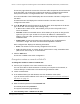


Table Of Contents
- 8-Port or 16-Port Gigabit Smart Managed Pro Switch with PoE+ and 2 SFP Ports
- Contents
- 1 Get Started
- Available publications
- Switch management and discovery overview
- Change the default IP address of the switch
- Discover or change the switch IP address
- About the user interfaces
- Access the local browser interface
- Change the language of the local browser interface
- Use the Device View of the local browser interface
- Interface naming conventions
- Configure interface settings
- Context–sensitive help and access to the support website
- Access the user manual online
- Register your product
- 2 Configure System Information
- View or define system information
- Configure the IP network settings for management access
- Configure the time settings
- Configure denial of service settings
- Configure the DNS settings
- Configure green Ethernet settings
- Use the Device View
- Configure Power over Ethernet
- Configure SNMP
- Configure LLDP
- Configure a DHCP L2 relay, DHCP snooping, and dynamic ARP inspection
- Set up PoE timer schedules
- 3 Configure Switching
- Configure the port settings
- Configure link aggregation groups
- Configure VLANs
- Configure a voice VLAN
- Configure Auto-VoIP
- Configure Spanning Tree Protocol
- Configure multicast
- Manage IGMP snooping
- Configure IGMP snooping
- Configure IGMP snooping for interfaces
- View, search, or clear the IGMP snooping table
- Configure IGMP snooping for VLANs
- Modify IGMP snooping settings for a VLAN
- Disable IGMP snooping on a VLAN and remove it from the table
- Configure one or more IGMP multicast router interfaces
- Configure an IGMP multicast router VLAN
- IGMP snooping querier overview
- Configure an IGMP snooping querier
- Configure an IGMP snooping querier for a VLAN
- Display the status of the IGMP snooping querier for VLANs
- Manage MLD snooping
- Enable MLD snooping
- Configure MLD snooping for interfaces
- Configure the MLD VLAN settings
- Modify the MLD snooping settings for a VLAN
- Remove MLD snooping from a VLAN
- Configure one or more MLD multicast router interfaces
- Configure an MLD multicast router VLAN
- Configure an MLD snooping querier
- Configure the MLD snooping querier VLAN settings
- Configure multicast VLAN registration
- View, search, and manage the MAC address table
- Configure Layer 2 loop protection
- 4 Configure Routing
- 5 Configure Quality of Service
- 6 Manage Device Security
- Change the device password for the local browser interface
- Manage the RADIUS settings
- Configure the TACACS+ settings
- Configure authentication lists
- Manage the Smart Control Center Utility
- Configure management access
- Control access with profiles and rules
- Configure port authentication
- Set up traffic control
- Configure access control lists
- Use the ACL Wizard to create a simple ACL
- Configure a MAC ACL
- Configure MAC ACL rules
- Configure MAC bindings
- View or delete MAC ACL bindings in the MAC binding table
- Configure a basic or extended IPv4 ACL
- Configure rules for a basic IPv4 ACL
- Configure rules for an extended IPv4 ACL
- Configure an IPv6 ACL
- Configure rules for an IPv6 ACL
- Configure IP ACL interface bindings
- View or delete IP ACL bindings in the IP ACL binding table
- Configure VLAN ACL bindings
- 7 Monitor the Switch and the Traffic
- 8 Maintain or Troubleshoot the Switch
- A Configuration Examples
- B Specifications and Default Settings

8-Port or 16-Port Gigabit Smart Managed Pro Switch Model GS418TPP, GS510TLP, and GS510TPP
Manage Device Security User Manual361
The default password is password.
The System Information page displays.
5. Select Security > ACL > Basic > MAC Binding T
able.
6. To delete a MAC ACL-to-interface binding, do the following:
a. Select the check box next to the interface.
b. Click the Delete button.
The binding is removed.
The following table describes the information that is displayed in the MAC binding table.
Table 85. MAC Binding Table
Field Description
Interface The interface of the ACL assigned.
Direction The selected packet filtering direction for the ACL.
ACL Type The type of ACL assigned to the selected interface and direction.
ACL ID The ACL name identifying the ACL assigned to the selected interface
and direction.
Sequence Number The sequence number signifying the order of the specified ACL relative
to other
ACLs assigned to the selected interface and direction.
Configure a basic or extended IPv4 ACL
An IPv4 ACL consists of a set of rules that are matched sequentially against a packet. When
a packet meets the match criteria of a rule, the specified rule action (Permit or Deny) is taken,
and the additional rules are not checked for a match. You must specify the interfaces to
which an IPv4 ACL applies, as well as whether it applies to inbound or outbound traffic.
Multiple steps are involved in defining an IPv4 ACL and applying it to the switch:
1. Add an IPv4 ACL ID (see
Add an IPv4 ACL on page 362).
The differences between a basic IPv4 ACL and an extended IPv4 ACL are as follows:
• Numbered ACL from 1 to 99. Creates a basic IPv4 ACL, which allows you to permit
or deny traffic from a source IP address.
•
Numbered ACL from 100 to 199. Creates an extended IPv4 ACL, which allows you
to permit or deny specific types of Layer 3 or Layer 4 traffic from a source IP address