
User Manual

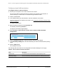

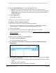


Table Of Contents
- 8-Port or 16-Port Gigabit Smart Managed Pro Switch with PoE+ and 2 SFP Ports
- Contents
- 1 Get Started
- Available publications
- Switch management and discovery overview
- Change the default IP address of the switch
- Discover or change the switch IP address
- About the user interfaces
- Access the local browser interface
- Change the language of the local browser interface
- Use the Device View of the local browser interface
- Interface naming conventions
- Configure interface settings
- Context–sensitive help and access to the support website
- Access the user manual online
- Register your product
- 2 Configure System Information
- View or define system information
- Configure the IP network settings for management access
- Configure the time settings
- Configure denial of service settings
- Configure the DNS settings
- Configure green Ethernet settings
- Use the Device View
- Configure Power over Ethernet
- Configure SNMP
- Configure LLDP
- Configure a DHCP L2 relay, DHCP snooping, and dynamic ARP inspection
- Set up PoE timer schedules
- 3 Configure Switching
- Configure the port settings
- Configure link aggregation groups
- Configure VLANs
- Configure a voice VLAN
- Configure Auto-VoIP
- Configure Spanning Tree Protocol
- Configure multicast
- Manage IGMP snooping
- Configure IGMP snooping
- Configure IGMP snooping for interfaces
- View, search, or clear the IGMP snooping table
- Configure IGMP snooping for VLANs
- Modify IGMP snooping settings for a VLAN
- Disable IGMP snooping on a VLAN and remove it from the table
- Configure one or more IGMP multicast router interfaces
- Configure an IGMP multicast router VLAN
- IGMP snooping querier overview
- Configure an IGMP snooping querier
- Configure an IGMP snooping querier for a VLAN
- Display the status of the IGMP snooping querier for VLANs
- Manage MLD snooping
- Enable MLD snooping
- Configure MLD snooping for interfaces
- Configure the MLD VLAN settings
- Modify the MLD snooping settings for a VLAN
- Remove MLD snooping from a VLAN
- Configure one or more MLD multicast router interfaces
- Configure an MLD multicast router VLAN
- Configure an MLD snooping querier
- Configure the MLD snooping querier VLAN settings
- Configure multicast VLAN registration
- View, search, and manage the MAC address table
- Configure Layer 2 loop protection
- 4 Configure Routing
- 5 Configure Quality of Service
- 6 Manage Device Security
- Change the device password for the local browser interface
- Manage the RADIUS settings
- Configure the TACACS+ settings
- Configure authentication lists
- Manage the Smart Control Center Utility
- Configure management access
- Control access with profiles and rules
- Configure port authentication
- Set up traffic control
- Configure access control lists
- Use the ACL Wizard to create a simple ACL
- Configure a MAC ACL
- Configure MAC ACL rules
- Configure MAC bindings
- View or delete MAC ACL bindings in the MAC binding table
- Configure a basic or extended IPv4 ACL
- Configure rules for a basic IPv4 ACL
- Configure rules for an extended IPv4 ACL
- Configure an IPv6 ACL
- Configure rules for an IPv6 ACL
- Configure IP ACL interface bindings
- View or delete IP ACL bindings in the IP ACL binding table
- Configure VLAN ACL bindings
- 7 Monitor the Switch and the Traffic
- 8 Maintain or Troubleshoot the Switch
- A Configuration Examples
- B Specifications and Default Settings

8-Port or 16-Port Gigabit Smart Managed Pro Switch Model GS418TPP, GS510TLP, and GS510TPP
Manage Device Security User Manual349
Note: For L4 port options, two rules are created (one for TCP and one for
UDP).
7. In the Sequence Number field, enter a whole number in the range of 1 to 2147483647 that
is used to identify the rule.
8. From the Action menu, select Permit or Deny to specify the action that must be taken if a
packet matches the rule’s criteria.
9. From the
Match Every menu, select one of the following options:
• False. Signifies that packets do not need to match the selected ACL and rule. With
this selection, you can add a destination MAC address, destination MAC mask, and
VLAN.
•
True. Signifies that all packets must match the selected ACL and rule and are either
permitted or denied. In this case, since all packets match the rule, the option of
configuring other match criteria is not of
fered.
10. Specify the additional match criteria for the selected ACL type.
The rest of the rule match criteria fields available for configuration depend on the selected
ACL type. For information about the possible match criteria fields, see the following table.
ACL Based On Fields
Destination MAC
• Destination MAC. Specify the destination MAC address to compare against
an Ethernet frame.
The valid format is xx:xx:xx:xx:xx:xx. The BPDU keyword
might be specified using a destination MAC address of 01:80:C2:xx:xx:xx.
• Destination MAC Mask. Specify the destination MAC address mask, which
represents the bits in the destination MAC address to compare against an
Ethernet frame. The valid format is xx:xx:xx:xx:xx:xx. The BPDU keyword
might be specified using a destination MAC mask of 00:00:00:ff:ff:ff.
• VLAN. Specify the VLAN ID to match within the Ethernet frame.
Source MAC
• Source MAC. Specify the source MAC address to compare against an
Ethernet frame. The valid format is xx:xx:xx:xx:xx:xx.
• Source MAC Mask. Specify the source MAC address mask, which
represents the bits in the source MAC address to compare against an
Ethernet frame. The valid format is (xx:xx:xx:xx:xx:xx).
• VLAN. Specify the VLAN ID to match within the Ethernet frame.
Destination IPv4
• Destination IP Address. Specify the destination IP address.
• Destination IP Mask. Specify the destination IP address mask.
Source IPv4
• Source IP Address. Specify the source IP address.
• Source IP Mask. Specify the source IP address mask.
Destination IPv6
• Destination Prefix. Specify the destination prefix.
• Destination Prefix Length. Specify the destination prefix length.
Source IPv6
• Source Prefix. Specify the source destination prefix.
• Source Prefix Length. Specify the source prefix length.
Destination IPv4 L4 Port
• Destination L4 port (protocol). Specify the destination IPv4 L4 port
protocol.
• Destination L4 port (value). Specify the destination IPv4 L4 port value.