
User Manual

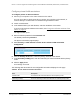

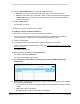


Table Of Contents
- 8-Port or 16-Port Gigabit Smart Managed Pro Switch with PoE+ and 2 SFP Ports
- Contents
- 1 Get Started
- Available publications
- Switch management and discovery overview
- Change the default IP address of the switch
- Discover or change the switch IP address
- About the user interfaces
- Access the local browser interface
- Change the language of the local browser interface
- Use the Device View of the local browser interface
- Interface naming conventions
- Configure interface settings
- Context–sensitive help and access to the support website
- Access the user manual online
- Register your product
- 2 Configure System Information
- View or define system information
- Configure the IP network settings for management access
- Configure the time settings
- Configure denial of service settings
- Configure the DNS settings
- Configure green Ethernet settings
- Use the Device View
- Configure Power over Ethernet
- Configure SNMP
- Configure LLDP
- Configure a DHCP L2 relay, DHCP snooping, and dynamic ARP inspection
- Set up PoE timer schedules
- 3 Configure Switching
- Configure the port settings
- Configure link aggregation groups
- Configure VLANs
- Configure a voice VLAN
- Configure Auto-VoIP
- Configure Spanning Tree Protocol
- Configure multicast
- Manage IGMP snooping
- Configure IGMP snooping
- Configure IGMP snooping for interfaces
- View, search, or clear the IGMP snooping table
- Configure IGMP snooping for VLANs
- Modify IGMP snooping settings for a VLAN
- Disable IGMP snooping on a VLAN and remove it from the table
- Configure one or more IGMP multicast router interfaces
- Configure an IGMP multicast router VLAN
- IGMP snooping querier overview
- Configure an IGMP snooping querier
- Configure an IGMP snooping querier for a VLAN
- Display the status of the IGMP snooping querier for VLANs
- Manage MLD snooping
- Enable MLD snooping
- Configure MLD snooping for interfaces
- Configure the MLD VLAN settings
- Modify the MLD snooping settings for a VLAN
- Remove MLD snooping from a VLAN
- Configure one or more MLD multicast router interfaces
- Configure an MLD multicast router VLAN
- Configure an MLD snooping querier
- Configure the MLD snooping querier VLAN settings
- Configure multicast VLAN registration
- View, search, and manage the MAC address table
- Configure Layer 2 loop protection
- 4 Configure Routing
- 5 Configure Quality of Service
- 6 Manage Device Security
- Change the device password for the local browser interface
- Manage the RADIUS settings
- Configure the TACACS+ settings
- Configure authentication lists
- Manage the Smart Control Center Utility
- Configure management access
- Control access with profiles and rules
- Configure port authentication
- Set up traffic control
- Configure access control lists
- Use the ACL Wizard to create a simple ACL
- Configure a MAC ACL
- Configure MAC ACL rules
- Configure MAC bindings
- View or delete MAC ACL bindings in the MAC binding table
- Configure a basic or extended IPv4 ACL
- Configure rules for a basic IPv4 ACL
- Configure rules for an extended IPv4 ACL
- Configure an IPv6 ACL
- Configure rules for an IPv6 ACL
- Configure IP ACL interface bindings
- View or delete IP ACL bindings in the IP ACL binding table
- Configure VLAN ACL bindings
- 7 Monitor the Switch and the Traffic
- 8 Maintain or Troubleshoot the Switch
- A Configuration Examples
- B Specifications and Default Settings

8-Port or 16-Port Gigabit Smart Managed Pro Switch Model GS418TPP, GS510TLP, and GS510TPP
Manage Device Security User Manual346
6. Select whether to display physical interfaces, LAGs, or both by clicking one of the following
links above the table heading:
•1 (the unit ID of the switch). Only physical interfaces are displayed.
This is the default
setting.
• LAG
. Only LAGs are displayed.
• All. Both physical interfaces and LAGs are displayed.
7. Select one or more interfaces by taking one of the following actions:
• T
o configure a single interface, select the check box associated with the port, or type
the port number in the Go T
o Interface field and click the Go button.
• To configure multiple interfaces with the same settings, select the check box
associated with each interface.
• To configure all interfaces with the same settings, select the check box in the heading
row
.
8. In the
Promiscuous Primary VLAN field, enter the primary VLAN ID for the promiscuous
association mode.
The range of the VLAN ID is 2–4093.
9. In the Promiscuous Secondary VLAN(s) field, enter the secondary VLAN ID for
promiscuous association mode.
This field can accept single a VLAN ID, a range of VLAN IDs, or a combination of both in
sequence separated by a comma.
You can specify an individual VLAN ID, such as 10.
Y
ou can specify the VLAN range values separated by a hyphen, for example, 10-13. You
can specify the combination of both separated by commas, for example,
12,15,40-43,1000-1005, 2000. The range of VLAN IDs is 2–4093.
Note: The VLAN ID list that you specify replaces the configured secondary
VLAN list in the association.
10. Click the Apply button.
Your settings are saved.
The Operational VLAN(s) field displays the operational VLANs.