
User Manual


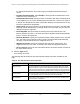
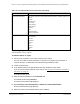

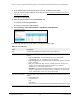


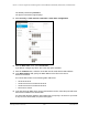
Table Of Contents
- 8-Port or 16-Port Gigabit Smart Managed Pro Switch with PoE+ and 2 SFP Ports
- Contents
- 1 Get Started
- Available publications
- Switch management and discovery overview
- Change the default IP address of the switch
- Discover or change the switch IP address
- About the user interfaces
- Access the local browser interface
- Change the language of the local browser interface
- Use the Device View of the local browser interface
- Interface naming conventions
- Configure interface settings
- Context–sensitive help and access to the support website
- Access the user manual online
- Register your product
- 2 Configure System Information
- View or define system information
- Configure the IP network settings for management access
- Configure the time settings
- Configure denial of service settings
- Configure the DNS settings
- Configure green Ethernet settings
- Use the Device View
- Configure Power over Ethernet
- Configure SNMP
- Configure LLDP
- Configure a DHCP L2 relay, DHCP snooping, and dynamic ARP inspection
- Set up PoE timer schedules
- 3 Configure Switching
- Configure the port settings
- Configure link aggregation groups
- Configure VLANs
- Configure a voice VLAN
- Configure Auto-VoIP
- Configure Spanning Tree Protocol
- Configure multicast
- Manage IGMP snooping
- Configure IGMP snooping
- Configure IGMP snooping for interfaces
- View, search, or clear the IGMP snooping table
- Configure IGMP snooping for VLANs
- Modify IGMP snooping settings for a VLAN
- Disable IGMP snooping on a VLAN and remove it from the table
- Configure one or more IGMP multicast router interfaces
- Configure an IGMP multicast router VLAN
- IGMP snooping querier overview
- Configure an IGMP snooping querier
- Configure an IGMP snooping querier for a VLAN
- Display the status of the IGMP snooping querier for VLANs
- Manage MLD snooping
- Enable MLD snooping
- Configure MLD snooping for interfaces
- Configure the MLD VLAN settings
- Modify the MLD snooping settings for a VLAN
- Remove MLD snooping from a VLAN
- Configure one or more MLD multicast router interfaces
- Configure an MLD multicast router VLAN
- Configure an MLD snooping querier
- Configure the MLD snooping querier VLAN settings
- Configure multicast VLAN registration
- View, search, and manage the MAC address table
- Configure Layer 2 loop protection
- 4 Configure Routing
- 5 Configure Quality of Service
- 6 Manage Device Security
- Change the device password for the local browser interface
- Manage the RADIUS settings
- Configure the TACACS+ settings
- Configure authentication lists
- Manage the Smart Control Center Utility
- Configure management access
- Control access with profiles and rules
- Configure port authentication
- Set up traffic control
- Configure access control lists
- Use the ACL Wizard to create a simple ACL
- Configure a MAC ACL
- Configure MAC ACL rules
- Configure MAC bindings
- View or delete MAC ACL bindings in the MAC binding table
- Configure a basic or extended IPv4 ACL
- Configure rules for a basic IPv4 ACL
- Configure rules for an extended IPv4 ACL
- Configure an IPv6 ACL
- Configure rules for an IPv6 ACL
- Configure IP ACL interface bindings
- View or delete IP ACL bindings in the IP ACL binding table
- Configure VLAN ACL bindings
- 7 Monitor the Switch and the Traffic
- 8 Maintain or Troubleshoot the Switch
- A Configuration Examples
- B Specifications and Default Settings

8-Port or 16-Port Gigabit Smart Managed Pro Switch Model GS418TPP, GS510TLP, and GS510TPP
Manage Device Security User Manual323
The previous figure shows only part of the page.
6. Use the horizontal scroll bar at the bottom of the page to view all the fields.
7. Select one or more interfaces by taking one of the following actions:
• To configure a single interface, select the check box associated with the port, or type
the port number in the Go T
o Interface field and click the Go button.
• To configure multiple interfaces with the same settings, select the check box
associated with each interface.
• To configure all interfaces with the same settings, select the check box in the heading
row.
8. Specify the following settings:
•
Port Control. Defines the port authorization state. The control mode is set only if the
link status of the port is link up. Select one of the following options:
- Auto
. The switch automatically detects the mode of the interface.
- Authorized
. The switch places the interface into an authorized state without
being authenticated. The interface sends and receives normal traf
fic without client
port-based authentication.
- Unauthorized. The switch denies the selected interface system access by
moving the interface into unauthorized state. The switch cannot provide
authentication services to the client through the interface.
-
MAC based. This mode allows multiple supplicants connected to the same port to
each authenticate individually. Each host connected to the port must authenticate
separately in order to gain access to the network.
The hosts are distinguished by
their MAC addresses.
• Guest VLAN ID. Specify the VLAN ID for the guest VLAN.
The valid range is 0–4093.
The default value is 0. Enter 0 to reset the guest VLAN ID on the interface. The guest
VLAN allows the port to provide a distinguished service to unauthenticated users,
after three authentication failures.
This feature provides a mechanism to allow users
access to hosts on the guest VLAN.
• Guest VLAN Period. Specify the number of seconds that the selected port remains
in the quiet state following a failed authentication exchange.
The guest VLAN time-out
must be a value in the range of 1–300. The default value is 90.
•
Unauthenticated VLAN ID. Specify the VLAN ID of the unauthenticated VLAN for the
selected port. The valid range is 0–3965. The default value is 0. Hosts that fail the
authentication might be denied access to the network or placed on a VLAN created