
User Manual


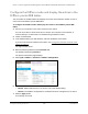


Table Of Contents
- 8-Port or 16-Port Gigabit Smart Managed Pro Switch with PoE+ and 2 SFP Ports
- Contents
- 1 Get Started
- Available publications
- Switch management and discovery overview
- Change the default IP address of the switch
- Discover or change the switch IP address
- About the user interfaces
- Access the local browser interface
- Change the language of the local browser interface
- Use the Device View of the local browser interface
- Interface naming conventions
- Configure interface settings
- Context–sensitive help and access to the support website
- Access the user manual online
- Register your product
- 2 Configure System Information
- View or define system information
- Configure the IP network settings for management access
- Configure the time settings
- Configure denial of service settings
- Configure the DNS settings
- Configure green Ethernet settings
- Use the Device View
- Configure Power over Ethernet
- Configure SNMP
- Configure LLDP
- Configure a DHCP L2 relay, DHCP snooping, and dynamic ARP inspection
- Set up PoE timer schedules
- 3 Configure Switching
- Configure the port settings
- Configure link aggregation groups
- Configure VLANs
- Configure a voice VLAN
- Configure Auto-VoIP
- Configure Spanning Tree Protocol
- Configure multicast
- Manage IGMP snooping
- Configure IGMP snooping
- Configure IGMP snooping for interfaces
- View, search, or clear the IGMP snooping table
- Configure IGMP snooping for VLANs
- Modify IGMP snooping settings for a VLAN
- Disable IGMP snooping on a VLAN and remove it from the table
- Configure one or more IGMP multicast router interfaces
- Configure an IGMP multicast router VLAN
- IGMP snooping querier overview
- Configure an IGMP snooping querier
- Configure an IGMP snooping querier for a VLAN
- Display the status of the IGMP snooping querier for VLANs
- Manage MLD snooping
- Enable MLD snooping
- Configure MLD snooping for interfaces
- Configure the MLD VLAN settings
- Modify the MLD snooping settings for a VLAN
- Remove MLD snooping from a VLAN
- Configure one or more MLD multicast router interfaces
- Configure an MLD multicast router VLAN
- Configure an MLD snooping querier
- Configure the MLD snooping querier VLAN settings
- Configure multicast VLAN registration
- View, search, and manage the MAC address table
- Configure Layer 2 loop protection
- 4 Configure Routing
- 5 Configure Quality of Service
- 6 Manage Device Security
- Change the device password for the local browser interface
- Manage the RADIUS settings
- Configure the TACACS+ settings
- Configure authentication lists
- Manage the Smart Control Center Utility
- Configure management access
- Control access with profiles and rules
- Configure port authentication
- Set up traffic control
- Configure access control lists
- Use the ACL Wizard to create a simple ACL
- Configure a MAC ACL
- Configure MAC ACL rules
- Configure MAC bindings
- View or delete MAC ACL bindings in the MAC binding table
- Configure a basic or extended IPv4 ACL
- Configure rules for a basic IPv4 ACL
- Configure rules for an extended IPv4 ACL
- Configure an IPv6 ACL
- Configure rules for an IPv6 ACL
- Configure IP ACL interface bindings
- View or delete IP ACL bindings in the IP ACL binding table
- Configure VLAN ACL bindings
- 7 Monitor the Switch and the Traffic
- 8 Maintain or Troubleshoot the Switch
- A Configuration Examples
- B Specifications and Default Settings

8-Port or 16-Port Gigabit Smart Managed Pro Switch Model GS418TPP, GS510TLP, and GS510TPP
Configure Quality of Service User Manual262
7. Select one or more interfaces by taking one of the following actions:
• To configure a single interface, select the check box associated with the port, or type
the port number in the
Go To Interface field and click the Go button.
• To configure multiple interfaces with the same settings, select the check box
associated with each interface.
• To configure all interfaces with the same settings, select the check box in the heading
row
.
8. From the Queue ID menu, select the queue to be configured.
9. In the Minimum Bandwidth field, specify the minimum guaranteed bandwidth allotted to the
queue.
Setting this value higher than its corresponding maximum bandwidth automatically
increases the maximum to the same value.
The default value is 0.
The valid range is 0 to
100 in increments of 1. The value 0 means no guaranteed minimum. The sum of the
individual minimum bandwidth values for all queues for the interface cannot exceed the
defined maximum (100).
10. From the Scheduler T
ype menu, select one of the following options:
•
Strict. The interface services traffic with the highest priority on a queue first.
•
Weighted. The interface uses weighted round robin to associate a weight to each
queue.
This is the default setting.
The Queue Management Type field displays the queue depth management technique
that is used for queues on the interface. By default, this method is Taildrop, irrespective of
your selection from the Scheduler Type menu.
11. Click the Apply button.
Your settings are saved.
Map 802.1p priorities to queues
You can view or change which internal traffic classes are mapped to the 802.1p priority class
values in Ethernet frames that the device receives. The priority-to-traffic class mappings can
be applied globally or per interface. The mapping allows the switch to group various traffic
types (for example, data or voice) based on their latency requirements and give preference to
time-sensitive traffic.
To map 802.1p priorities to queues:
1. Connect your computer to the same network as the switch.
You can use a WiFi or wired connection to connect your computer to the network, or
connect directly to a switch that is of
f-network using an Ethernet cable.
2. Launch a web browser.
3. In the address field of your web browser, enter the IP address of the switch.