
User Manual


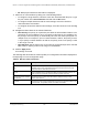


Table Of Contents
- 8-Port or 16-Port Gigabit Smart Managed Pro Switch with PoE+ and 2 SFP Ports
- Contents
- 1 Get Started
- Available publications
- Switch management and discovery overview
- Change the default IP address of the switch
- Discover or change the switch IP address
- About the user interfaces
- Access the local browser interface
- Change the language of the local browser interface
- Use the Device View of the local browser interface
- Interface naming conventions
- Configure interface settings
- Context–sensitive help and access to the support website
- Access the user manual online
- Register your product
- 2 Configure System Information
- View or define system information
- Configure the IP network settings for management access
- Configure the time settings
- Configure denial of service settings
- Configure the DNS settings
- Configure green Ethernet settings
- Use the Device View
- Configure Power over Ethernet
- Configure SNMP
- Configure LLDP
- Configure a DHCP L2 relay, DHCP snooping, and dynamic ARP inspection
- Set up PoE timer schedules
- 3 Configure Switching
- Configure the port settings
- Configure link aggregation groups
- Configure VLANs
- Configure a voice VLAN
- Configure Auto-VoIP
- Configure Spanning Tree Protocol
- Configure multicast
- Manage IGMP snooping
- Configure IGMP snooping
- Configure IGMP snooping for interfaces
- View, search, or clear the IGMP snooping table
- Configure IGMP snooping for VLANs
- Modify IGMP snooping settings for a VLAN
- Disable IGMP snooping on a VLAN and remove it from the table
- Configure one or more IGMP multicast router interfaces
- Configure an IGMP multicast router VLAN
- IGMP snooping querier overview
- Configure an IGMP snooping querier
- Configure an IGMP snooping querier for a VLAN
- Display the status of the IGMP snooping querier for VLANs
- Manage MLD snooping
- Enable MLD snooping
- Configure MLD snooping for interfaces
- Configure the MLD VLAN settings
- Modify the MLD snooping settings for a VLAN
- Remove MLD snooping from a VLAN
- Configure one or more MLD multicast router interfaces
- Configure an MLD multicast router VLAN
- Configure an MLD snooping querier
- Configure the MLD snooping querier VLAN settings
- Configure multicast VLAN registration
- View, search, and manage the MAC address table
- Configure Layer 2 loop protection
- 4 Configure Routing
- 5 Configure Quality of Service
- 6 Manage Device Security
- Change the device password for the local browser interface
- Manage the RADIUS settings
- Configure the TACACS+ settings
- Configure authentication lists
- Manage the Smart Control Center Utility
- Configure management access
- Control access with profiles and rules
- Configure port authentication
- Set up traffic control
- Configure access control lists
- Use the ACL Wizard to create a simple ACL
- Configure a MAC ACL
- Configure MAC ACL rules
- Configure MAC bindings
- View or delete MAC ACL bindings in the MAC binding table
- Configure a basic or extended IPv4 ACL
- Configure rules for a basic IPv4 ACL
- Configure rules for an extended IPv4 ACL
- Configure an IPv6 ACL
- Configure rules for an IPv6 ACL
- Configure IP ACL interface bindings
- View or delete IP ACL bindings in the IP ACL binding table
- Configure VLAN ACL bindings
- 7 Monitor the Switch and the Traffic
- 8 Maintain or Troubleshoot the Switch
- A Configuration Examples
- B Specifications and Default Settings

8-Port or 16-Port Gigabit Smart Managed Pro Switch Model GS418TPP, GS510TLP, and GS510TPP
Configure Switching User Manual177
View the STP statistics
You can view information about the number and type of bridge protocol data units (BPDUs)
transmitted and received on each port.
To view the spanning tree statistics:
1. Connect your computer to the same network as the switch.
You can use a WiFi or wired connection to connect your computer to the network, or
connect directly to a switch that is off-network using an Ethernet cable.
2. Launch a web browser.
3. In the address field of your web browser, enter the IP address of the switch.
If you do not know the IP address of the switch, see
Change the default IP address of
the switch on page 13.
The login window opens.
4. Enter the switch’s password in the Password
field.
Port Forwarding State Indicates the current STP state of a port. If enabled, the port state determines
what forwarding action is taken on traffic. Possible port states are as follows:
• Disabled. STP is currently disabled on the port.
The port forwards traf
fic
while learning MAC addresses.
• Blocking. The port is currently blocked and cannot be used to forward
traffic or learn MAC addresses.
• Listening. The port is currently in the listening mode. The port cannot
forward traffic nor can it learn MAC addresses.
• Learning. The port is currently in the learning mode. The port cannot
forward traffic. However, it can learn new MAC addresses.
• Forwarding. The port is currently in the forwarding mode. The port can
forward traffic and learn new MAC addresses
Port Role Each MST bridge port that is enabled is assigned a port role for each spanning
tree.
The port role is one of the following: Root Port, Designated Port,
Alternate
Port, Backup Port, Master Port, or Disabled Port.
Designated Root The root bridge for the selected MST instance. It is made up using the bridge
priority and the base MAC address of the bridge.
Designated Cost The cost of the port participating in the STP topology. Ports with a lower cost are
less likely to be blocked if STP detects loops.
Designated Bridge The bridge identifier of the bridge with the designated port. It is made up using
the bridge priority and the base MAC address of the bridge.
Designated Port The port identifier on the designated bridge that offers the lowest cost to the
LAN. It is made up from the port priority and the interface number of the port.
Table 43. MST port status information (continued)
Field Description