
User Manual


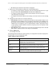


Table Of Contents
- 8-Port or 16-Port Gigabit Smart Managed Pro Switch with PoE+ and 2 SFP Ports
- Contents
- 1 Get Started
- Available publications
- Switch management and discovery overview
- Change the default IP address of the switch
- Discover or change the switch IP address
- About the user interfaces
- Access the local browser interface
- Change the language of the local browser interface
- Use the Device View of the local browser interface
- Interface naming conventions
- Configure interface settings
- Context–sensitive help and access to the support website
- Access the user manual online
- Register your product
- 2 Configure System Information
- View or define system information
- Configure the IP network settings for management access
- Configure the time settings
- Configure denial of service settings
- Configure the DNS settings
- Configure green Ethernet settings
- Use the Device View
- Configure Power over Ethernet
- Configure SNMP
- Configure LLDP
- Configure a DHCP L2 relay, DHCP snooping, and dynamic ARP inspection
- Set up PoE timer schedules
- 3 Configure Switching
- Configure the port settings
- Configure link aggregation groups
- Configure VLANs
- Configure a voice VLAN
- Configure Auto-VoIP
- Configure Spanning Tree Protocol
- Configure multicast
- Manage IGMP snooping
- Configure IGMP snooping
- Configure IGMP snooping for interfaces
- View, search, or clear the IGMP snooping table
- Configure IGMP snooping for VLANs
- Modify IGMP snooping settings for a VLAN
- Disable IGMP snooping on a VLAN and remove it from the table
- Configure one or more IGMP multicast router interfaces
- Configure an IGMP multicast router VLAN
- IGMP snooping querier overview
- Configure an IGMP snooping querier
- Configure an IGMP snooping querier for a VLAN
- Display the status of the IGMP snooping querier for VLANs
- Manage MLD snooping
- Enable MLD snooping
- Configure MLD snooping for interfaces
- Configure the MLD VLAN settings
- Modify the MLD snooping settings for a VLAN
- Remove MLD snooping from a VLAN
- Configure one or more MLD multicast router interfaces
- Configure an MLD multicast router VLAN
- Configure an MLD snooping querier
- Configure the MLD snooping querier VLAN settings
- Configure multicast VLAN registration
- View, search, and manage the MAC address table
- Configure Layer 2 loop protection
- 4 Configure Routing
- 5 Configure Quality of Service
- 6 Manage Device Security
- Change the device password for the local browser interface
- Manage the RADIUS settings
- Configure the TACACS+ settings
- Configure authentication lists
- Manage the Smart Control Center Utility
- Configure management access
- Control access with profiles and rules
- Configure port authentication
- Set up traffic control
- Configure access control lists
- Use the ACL Wizard to create a simple ACL
- Configure a MAC ACL
- Configure MAC ACL rules
- Configure MAC bindings
- View or delete MAC ACL bindings in the MAC binding table
- Configure a basic or extended IPv4 ACL
- Configure rules for a basic IPv4 ACL
- Configure rules for an extended IPv4 ACL
- Configure an IPv6 ACL
- Configure rules for an IPv6 ACL
- Configure IP ACL interface bindings
- View or delete IP ACL bindings in the IP ACL binding table
- Configure VLAN ACL bindings
- 7 Monitor the Switch and the Traffic
- 8 Maintain or Troubleshoot the Switch
- A Configuration Examples
- B Specifications and Default Settings

8-Port or 16-Port Gigabit Smart Managed Pro Switch Model GS418TPP, GS510TLP, and GS510TPP
Configure Switching User Manual173
6. Configure the MST values:
• MST ID. Specify the ID of the MST to create. The valid values for this are 1 to 4094.
This is visible only when the select option of the MST ID select box is selected.
• Priority. The bridge priority value for the MST. When switches or bridges are running
STP
, each is assigned a priority. After exchanging BPDUs, the switch with the lowest
priority value becomes the root bridge. The bridge priority is a multiple of 4096. If you
specify a priority that is not a multiple of 4096, the priority is automatically set to the
next lowest priority that is a multiple of 4096. For example, if you set the priority to any
value between 0 and 4095, the switch automatically sets the value to 0. The default
value is 32768. The valid range is 0–61440.
• VLAN Id.
The menu includes all VLANs that are configured on the switch. Y
ou can
select VLANs that must be associated with the MST instance or clear VLANs that are
already associated with the MST instance.
7. Click the Add button.
The MST is added.
For each configured instance, the information described in the following table displays on the
page.
Table 42. MST configuration
Field Description
Bridge Identifier The bridge identifier for the selected MST instance. It is made up using the bridge
priority and the base MAC address of the bridge.
Last TCN The time in day:hour:minute:second format since the topology of the selected
MST instance last changed.
Topology Change Count Number of times that the topology changed for the selected MST instance.
Topology Change The value of the topology change parameter for the switch indicating if a topology
change is in progress on any port assigned to the selected MST instance. It is
either
True or False.
Designated Root The bridge identifier of the root bridge. It is made up from the bridge priority and
the base MAC address of the bridge
Root Path Cost Path cost to the designated root for this MST instance.
Root Port Port to access the designated root for this MST instance.