
User Manual
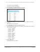

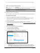

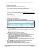


Table Of Contents
- 8-Port or 16-Port Gigabit Smart Managed Pro Switch with PoE+ and 2 SFP Ports
- Contents
- 1 Get Started
- Available publications
- Switch management and discovery overview
- Change the default IP address of the switch
- Discover or change the switch IP address
- About the user interfaces
- Access the local browser interface
- Change the language of the local browser interface
- Use the Device View of the local browser interface
- Interface naming conventions
- Configure interface settings
- Context–sensitive help and access to the support website
- Access the user manual online
- Register your product
- 2 Configure System Information
- View or define system information
- Configure the IP network settings for management access
- Configure the time settings
- Configure denial of service settings
- Configure the DNS settings
- Configure green Ethernet settings
- Use the Device View
- Configure Power over Ethernet
- Configure SNMP
- Configure LLDP
- Configure a DHCP L2 relay, DHCP snooping, and dynamic ARP inspection
- Set up PoE timer schedules
- 3 Configure Switching
- Configure the port settings
- Configure link aggregation groups
- Configure VLANs
- Configure a voice VLAN
- Configure Auto-VoIP
- Configure Spanning Tree Protocol
- Configure multicast
- Manage IGMP snooping
- Configure IGMP snooping
- Configure IGMP snooping for interfaces
- View, search, or clear the IGMP snooping table
- Configure IGMP snooping for VLANs
- Modify IGMP snooping settings for a VLAN
- Disable IGMP snooping on a VLAN and remove it from the table
- Configure one or more IGMP multicast router interfaces
- Configure an IGMP multicast router VLAN
- IGMP snooping querier overview
- Configure an IGMP snooping querier
- Configure an IGMP snooping querier for a VLAN
- Display the status of the IGMP snooping querier for VLANs
- Manage MLD snooping
- Enable MLD snooping
- Configure MLD snooping for interfaces
- Configure the MLD VLAN settings
- Modify the MLD snooping settings for a VLAN
- Remove MLD snooping from a VLAN
- Configure one or more MLD multicast router interfaces
- Configure an MLD multicast router VLAN
- Configure an MLD snooping querier
- Configure the MLD snooping querier VLAN settings
- Configure multicast VLAN registration
- View, search, and manage the MAC address table
- Configure Layer 2 loop protection
- 4 Configure Routing
- 5 Configure Quality of Service
- 6 Manage Device Security
- Change the device password for the local browser interface
- Manage the RADIUS settings
- Configure the TACACS+ settings
- Configure authentication lists
- Manage the Smart Control Center Utility
- Configure management access
- Control access with profiles and rules
- Configure port authentication
- Set up traffic control
- Configure access control lists
- Use the ACL Wizard to create a simple ACL
- Configure a MAC ACL
- Configure MAC ACL rules
- Configure MAC bindings
- View or delete MAC ACL bindings in the MAC binding table
- Configure a basic or extended IPv4 ACL
- Configure rules for a basic IPv4 ACL
- Configure rules for an extended IPv4 ACL
- Configure an IPv6 ACL
- Configure rules for an IPv6 ACL
- Configure IP ACL interface bindings
- View or delete IP ACL bindings in the IP ACL binding table
- Configure VLAN ACL bindings
- 7 Monitor the Switch and the Traffic
- 8 Maintain or Troubleshoot the Switch
- A Configuration Examples
- B Specifications and Default Settings

8-Port or 16-Port Gigabit Smart Managed Pro Switch Model GS418TPP, GS510TLP, and GS510TPP
Configure Switching User Manual169
The possible values are Enable and Disable. The default value is Disable.
10. From the BPDU Forwarding menu, configure BPDU forwarding.
The possible values are Enable and Disable. The default value is Disable. When BPDU
forwarding is enabled, the switch forwards the BPDU traffic arriving on this port when
STP is disabled on this port.
1
1. From the Auto Edge menu, specify if the port is allowed to become an edge port if it does
not detect BPDUs for some duration.
The possible values are Enable and Disable. The default value is Enable.
12. In the Path Cost field, set the path cost to a new value for the specified port in the common
and internal spanning tree.
Specify a value in the range of 0 to 200000000.
The default is 0. When the path cost is
set to 0, the value is updated with the external path cost from a received STP packet.
13. In the Priority field, specify the priority for a particular port within the CST.
The port priority is set in multiples of 16. For example if you attempt to set the priority to
any value between 0 and 15, it is set to 0. If you try to set it to any value between 16 and
(2*16 – 1), it is set to 16, and so on. The range is 0 to 240.
The default value is 128.
14. In the
External Port Path Cost field, set the external path cost to a new value for the
specified port in the spanning tree.
The value range is 0 to 200000000. The default is 0.
15. Click the Apply button.
Your settings are saved.
16. T
o refresh the page with the latest information about the switch, click the Update button.
The following table describes the nonconfigurable information displayed on the page.
Table 39. CST port configuration
Field Description
Port State The forwarding state of this port. The default is Disabled.
Port ID The port identifier for the specified port within the CST. It is made up
from the port priority and the interface number of the port.
Hello Timer The value of the parameter for the CST. The default is 2 seconds.