
User Manual
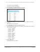

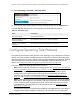
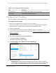

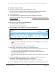


Table Of Contents
- 8-Port or 16-Port Gigabit Smart Managed Pro Switch with PoE+ and 2 SFP Ports
- Contents
- 1 Get Started
- Available publications
- Switch management and discovery overview
- Change the default IP address of the switch
- Discover or change the switch IP address
- About the user interfaces
- Access the local browser interface
- Change the language of the local browser interface
- Use the Device View of the local browser interface
- Interface naming conventions
- Configure interface settings
- Context–sensitive help and access to the support website
- Access the user manual online
- Register your product
- 2 Configure System Information
- View or define system information
- Configure the IP network settings for management access
- Configure the time settings
- Configure denial of service settings
- Configure the DNS settings
- Configure green Ethernet settings
- Use the Device View
- Configure Power over Ethernet
- Configure SNMP
- Configure LLDP
- Configure a DHCP L2 relay, DHCP snooping, and dynamic ARP inspection
- Set up PoE timer schedules
- 3 Configure Switching
- Configure the port settings
- Configure link aggregation groups
- Configure VLANs
- Configure a voice VLAN
- Configure Auto-VoIP
- Configure Spanning Tree Protocol
- Configure multicast
- Manage IGMP snooping
- Configure IGMP snooping
- Configure IGMP snooping for interfaces
- View, search, or clear the IGMP snooping table
- Configure IGMP snooping for VLANs
- Modify IGMP snooping settings for a VLAN
- Disable IGMP snooping on a VLAN and remove it from the table
- Configure one or more IGMP multicast router interfaces
- Configure an IGMP multicast router VLAN
- IGMP snooping querier overview
- Configure an IGMP snooping querier
- Configure an IGMP snooping querier for a VLAN
- Display the status of the IGMP snooping querier for VLANs
- Manage MLD snooping
- Enable MLD snooping
- Configure MLD snooping for interfaces
- Configure the MLD VLAN settings
- Modify the MLD snooping settings for a VLAN
- Remove MLD snooping from a VLAN
- Configure one or more MLD multicast router interfaces
- Configure an MLD multicast router VLAN
- Configure an MLD snooping querier
- Configure the MLD snooping querier VLAN settings
- Configure multicast VLAN registration
- View, search, and manage the MAC address table
- Configure Layer 2 loop protection
- 4 Configure Routing
- 5 Configure Quality of Service
- 6 Manage Device Security
- Change the device password for the local browser interface
- Manage the RADIUS settings
- Configure the TACACS+ settings
- Configure authentication lists
- Manage the Smart Control Center Utility
- Configure management access
- Control access with profiles and rules
- Configure port authentication
- Set up traffic control
- Configure access control lists
- Use the ACL Wizard to create a simple ACL
- Configure a MAC ACL
- Configure MAC ACL rules
- Configure MAC bindings
- View or delete MAC ACL bindings in the MAC binding table
- Configure a basic or extended IPv4 ACL
- Configure rules for a basic IPv4 ACL
- Configure rules for an extended IPv4 ACL
- Configure an IPv6 ACL
- Configure rules for an IPv6 ACL
- Configure IP ACL interface bindings
- View or delete IP ACL bindings in the IP ACL binding table
- Configure VLAN ACL bindings
- 7 Monitor the Switch and the Traffic
- 8 Maintain or Troubleshoot the Switch
- A Configuration Examples
- B Specifications and Default Settings

8-Port or 16-Port Gigabit Smart Managed Pro Switch Model GS418TPP, GS510TLP, and GS510TPP
Configure Switching User Manual163
5. Select Switching > Auto-VoIP > Auto-VoIP Status.
6. To refresh the page with the latest information about the switch, click the Update button.
The following table describes the nonconfigurable Auto-VoIP status information.
Table 36. Auto-VoIP status
Field Description
Auto-VoIP VLAN ID The Auto-VoIP VLAN ID.
Maximum Number of Voice
Channels Supported
The maximum number of voice channels supported.
Number of Voice Channels
Detected
The number of VoIP channels prioritized successfully.
Configure Spanning Tree Protocol
The Spanning Tree Protocol (STP) provides a tree topology for any arrangement of network
devices. STP also provides one path between end stations on a network, eliminating loops.
STP (also referred to as “classic” STP) provides a single path between end stations, avoiding
and eliminating loops. For information about configuring the global STP settings for the
switch, see
Configure the STP settings and view the STP status on page 164.
The switch support the following spanning tree versions:
• CST. Common STP. For information on configuring CST, see
Configure the CST settings
on page 166 and Configure the CST port settings on page 167.
• MSTP. Multiple Spanning Tree Protocol (MSTP
, also referred to as MST) supports
multiple instances of spanning tree to efficiently channel VLAN traffic over different
interfaces. For information on configuring MSTP, see
Manage the MST settings on
page 172 and Configure and view the port settings for an MST instance on page 175.
• RSTP. Rapid STP. Each instance of the spanning tree behaves in the manner specified in
IEEE 802.1w, Rapid Spanning
Tree (RSTP), with slight modifications in the working but
not the end effect (chief among the effects is the rapid transitioning of the port to the
forwarding state). For information on viewing the RSTP state, see
View Rapid STP
Information on page 171.
The difference between the RSTP and the traditional STP (IEEE 802.1D) is the ability to
configure and recognize full-duplex connectivity and ports that are connected to end