
User Manual


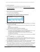


Table Of Contents
- 8-Port or 16-Port Gigabit Smart Managed Pro Switch with PoE+ and 2 SFP Ports
- Contents
- 1 Get Started
- Available publications
- Switch management and discovery overview
- Change the default IP address of the switch
- Discover or change the switch IP address
- About the user interfaces
- Access the local browser interface
- Change the language of the local browser interface
- Use the Device View of the local browser interface
- Interface naming conventions
- Configure interface settings
- Context–sensitive help and access to the support website
- Access the user manual online
- Register your product
- 2 Configure System Information
- View or define system information
- Configure the IP network settings for management access
- Configure the time settings
- Configure denial of service settings
- Configure the DNS settings
- Configure green Ethernet settings
- Use the Device View
- Configure Power over Ethernet
- Configure SNMP
- Configure LLDP
- Configure a DHCP L2 relay, DHCP snooping, and dynamic ARP inspection
- Set up PoE timer schedules
- 3 Configure Switching
- Configure the port settings
- Configure link aggregation groups
- Configure VLANs
- Configure a voice VLAN
- Configure Auto-VoIP
- Configure Spanning Tree Protocol
- Configure multicast
- Manage IGMP snooping
- Configure IGMP snooping
- Configure IGMP snooping for interfaces
- View, search, or clear the IGMP snooping table
- Configure IGMP snooping for VLANs
- Modify IGMP snooping settings for a VLAN
- Disable IGMP snooping on a VLAN and remove it from the table
- Configure one or more IGMP multicast router interfaces
- Configure an IGMP multicast router VLAN
- IGMP snooping querier overview
- Configure an IGMP snooping querier
- Configure an IGMP snooping querier for a VLAN
- Display the status of the IGMP snooping querier for VLANs
- Manage MLD snooping
- Enable MLD snooping
- Configure MLD snooping for interfaces
- Configure the MLD VLAN settings
- Modify the MLD snooping settings for a VLAN
- Remove MLD snooping from a VLAN
- Configure one or more MLD multicast router interfaces
- Configure an MLD multicast router VLAN
- Configure an MLD snooping querier
- Configure the MLD snooping querier VLAN settings
- Configure multicast VLAN registration
- View, search, and manage the MAC address table
- Configure Layer 2 loop protection
- 4 Configure Routing
- 5 Configure Quality of Service
- 6 Manage Device Security
- Change the device password for the local browser interface
- Manage the RADIUS settings
- Configure the TACACS+ settings
- Configure authentication lists
- Manage the Smart Control Center Utility
- Configure management access
- Control access with profiles and rules
- Configure port authentication
- Set up traffic control
- Configure access control lists
- Use the ACL Wizard to create a simple ACL
- Configure a MAC ACL
- Configure MAC ACL rules
- Configure MAC bindings
- View or delete MAC ACL bindings in the MAC binding table
- Configure a basic or extended IPv4 ACL
- Configure rules for a basic IPv4 ACL
- Configure rules for an extended IPv4 ACL
- Configure an IPv6 ACL
- Configure rules for an IPv6 ACL
- Configure IP ACL interface bindings
- View or delete IP ACL bindings in the IP ACL binding table
- Configure VLAN ACL bindings
- 7 Monitor the Switch and the Traffic
- 8 Maintain or Troubleshoot the Switch
- A Configuration Examples
- B Specifications and Default Settings

8-Port or 16-Port Gigabit Smart Managed Pro Switch Model GS418TPP, GS510TLP, and GS510TPP
Configure Switching User Manual153
8. From the Interface Mode menu, select the voice VLAN mode for selected interfaces:
• Disable. This is the default value.
•
None. Allow the IP phone to use its own configuration to send untagged voice traffic.
•
VLAN ID. Configure the phone to send tagged voice traffic.
•
dot1p. Configure voice VLAN 802.1p priority tagging for voice traffic. When this is
selected, enter the dot1p value in the
Value field.
• Untagged. Configure the phone to send untagged voice traffic.
9. In the
Value field, enter the VLAN ID or dot1p value.
This field is enabled only when VLAN ID or dot1p is selected as the interface mode.
10. In the
CoS Override Mode field, select Disable or Enable.
The default is Disable.
11. In the Authentication Mode field, select Enable or Disable.
The default is Enable. When the authentication mode is enabled, voice traffic is allowed
on an unauthorized voice VLAN port. When the authentication mode is disabled, devices
are authorized through dot1x.
Note: Authentication through dot1x is possible only if dot1x is enabled.
12. In the DSCP Value
field, configure the Voice VLAN DSCP value for the port.
The valid range is 0 to 64. The default value is 0.
The Operational State field displays the operational status of the voice VLAN on the given
interface.
13. Click the Apply button.
Your settings are saved.
Configure GARP switch settings
The Generic Attribute Registration Protocol (GARP) is used to exchange information
between GARP participants to register and deregister attribute values within a bridged LAN.
When a GARP participant declares or withdraws a given attribute, the attribute value is
recorded with the applicant state machine for that attribute, for the port from which the
declaration or withdrawal was made.
• Registration occurs only on ports that receive the GARP PDU containing a declaration or
withdrawal.
• Deregistration occurs only if all GARP participants connected to the same LAN segment
as the port withdraw the declaration.
GARP is part of the IEEE 802.1p extension to its 802.1D (spanning tree) specification. It
includes the following:
• GARP Information Declaration (GID). The part of GARP that generates data.
•
GARP Information Propagation (GIP). The part of GARP that distributes data.