
User Manual


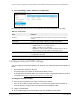


Table Of Contents
- 8-Port or 16-Port Gigabit Smart Managed Pro Switch with PoE+ and 2 SFP Ports
- Contents
- 1 Get Started
- Available publications
- Switch management and discovery overview
- Change the default IP address of the switch
- Discover or change the switch IP address
- About the user interfaces
- Access the local browser interface
- Change the language of the local browser interface
- Use the Device View of the local browser interface
- Interface naming conventions
- Configure interface settings
- Context–sensitive help and access to the support website
- Access the user manual online
- Register your product
- 2 Configure System Information
- View or define system information
- Configure the IP network settings for management access
- Configure the time settings
- Configure denial of service settings
- Configure the DNS settings
- Configure green Ethernet settings
- Use the Device View
- Configure Power over Ethernet
- Configure SNMP
- Configure LLDP
- Configure a DHCP L2 relay, DHCP snooping, and dynamic ARP inspection
- Set up PoE timer schedules
- 3 Configure Switching
- Configure the port settings
- Configure link aggregation groups
- Configure VLANs
- Configure a voice VLAN
- Configure Auto-VoIP
- Configure Spanning Tree Protocol
- Configure multicast
- Manage IGMP snooping
- Configure IGMP snooping
- Configure IGMP snooping for interfaces
- View, search, or clear the IGMP snooping table
- Configure IGMP snooping for VLANs
- Modify IGMP snooping settings for a VLAN
- Disable IGMP snooping on a VLAN and remove it from the table
- Configure one or more IGMP multicast router interfaces
- Configure an IGMP multicast router VLAN
- IGMP snooping querier overview
- Configure an IGMP snooping querier
- Configure an IGMP snooping querier for a VLAN
- Display the status of the IGMP snooping querier for VLANs
- Manage MLD snooping
- Enable MLD snooping
- Configure MLD snooping for interfaces
- Configure the MLD VLAN settings
- Modify the MLD snooping settings for a VLAN
- Remove MLD snooping from a VLAN
- Configure one or more MLD multicast router interfaces
- Configure an MLD multicast router VLAN
- Configure an MLD snooping querier
- Configure the MLD snooping querier VLAN settings
- Configure multicast VLAN registration
- View, search, and manage the MAC address table
- Configure Layer 2 loop protection
- 4 Configure Routing
- 5 Configure Quality of Service
- 6 Manage Device Security
- Change the device password for the local browser interface
- Manage the RADIUS settings
- Configure the TACACS+ settings
- Configure authentication lists
- Manage the Smart Control Center Utility
- Configure management access
- Control access with profiles and rules
- Configure port authentication
- Set up traffic control
- Configure access control lists
- Use the ACL Wizard to create a simple ACL
- Configure a MAC ACL
- Configure MAC ACL rules
- Configure MAC bindings
- View or delete MAC ACL bindings in the MAC binding table
- Configure a basic or extended IPv4 ACL
- Configure rules for a basic IPv4 ACL
- Configure rules for an extended IPv4 ACL
- Configure an IPv6 ACL
- Configure rules for an IPv6 ACL
- Configure IP ACL interface bindings
- View or delete IP ACL bindings in the IP ACL binding table
- Configure VLAN ACL bindings
- 7 Monitor the Switch and the Traffic
- 8 Maintain or Troubleshoot the Switch
- A Configuration Examples
- B Specifications and Default Settings

8-Port or 16-Port Gigabit Smart Managed Pro Switch Model GS418TPP, GS510TLP, and GS510TPP
Configure Switching User Manual149
3. In the address field of your web browser, enter the IP address of the switch.
If you do not know the IP address of the switch, see
Change the default IP address of
the switch on page 13.
The login window opens.
4. Enter the switch’s password in the Password
field.
The default password is password.
The System Information page displays.
5. Select Switching> VLAN >
Advanced > MAC Based VLAN
.
The MAC Based VLAN Configuration page displays.
6. In the MAC Address field, enter a valid MAC address.
This field is configurable only when a MAC-based VLAN exists.
7. In the VLAN ID field, specify a VLAN ID in the range of 1 to 4093.
8. Click the Delete button.
The MAC address is removed from the VLAN mapping.
Configure protocol-based VLAN groups
You can use a protocol-based VLAN to define filtering criteria for untagged packets. By
default, if you do not configure any port-based (IEEE 802.1Q) or protocol-based VLANs,
untagged packets are assigned to VLAN 1. You can override this behavior by defining either
port-based VLANs or protocol-based VLANs, or both. Tagged packets are always handled
according to the IEEE 802.1Q standard and are not included in protocol-based VLANs.
If you assign a port to a protocol-based VLAN for a specific protocol, untagged frames
received on that port for that protocol are assigned the protocol-based VLAN ID. Untagged
frames received on the port for other protocols are assigned the port VLAN ID, either the
default PVID (1) or a PVID you specifically assigned to the port using the Port VLAN
Configuration page.
You define a protocol-based VLAN by creating a group. Each group forms a one-to-one
relationship with a VLAN ID, can include one to three protocol definitions, and can include
multiple ports. When you create a group, you specify a name and a group ID is assigned
automatically
.
T
o configure a protocol-based VLAN group:
1. Connect your computer to the same network as the switch.
You can use a WiFi or wired connection to connect your computer to the network, or
connect directly to a switch that is of
f-network using an Ethernet cable.
2. Launch a web browser.
3. In the address field of your web browser, enter the IP address of the switch.