
User Manual


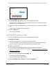

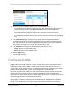
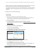
Table Of Contents
- 8-Port or 16-Port Gigabit Smart Managed Pro Switch with PoE+ and 2 SFP Ports
- Contents
- 1 Get Started
- Available publications
- Switch management and discovery overview
- Change the default IP address of the switch
- Discover or change the switch IP address
- About the user interfaces
- Access the local browser interface
- Change the language of the local browser interface
- Use the Device View of the local browser interface
- Interface naming conventions
- Configure interface settings
- Context–sensitive help and access to the support website
- Access the user manual online
- Register your product
- 2 Configure System Information
- View or define system information
- Configure the IP network settings for management access
- Configure the time settings
- Configure denial of service settings
- Configure the DNS settings
- Configure green Ethernet settings
- Use the Device View
- Configure Power over Ethernet
- Configure SNMP
- Configure LLDP
- Configure a DHCP L2 relay, DHCP snooping, and dynamic ARP inspection
- Set up PoE timer schedules
- 3 Configure Switching
- Configure the port settings
- Configure link aggregation groups
- Configure VLANs
- Configure a voice VLAN
- Configure Auto-VoIP
- Configure Spanning Tree Protocol
- Configure multicast
- Manage IGMP snooping
- Configure IGMP snooping
- Configure IGMP snooping for interfaces
- View, search, or clear the IGMP snooping table
- Configure IGMP snooping for VLANs
- Modify IGMP snooping settings for a VLAN
- Disable IGMP snooping on a VLAN and remove it from the table
- Configure one or more IGMP multicast router interfaces
- Configure an IGMP multicast router VLAN
- IGMP snooping querier overview
- Configure an IGMP snooping querier
- Configure an IGMP snooping querier for a VLAN
- Display the status of the IGMP snooping querier for VLANs
- Manage MLD snooping
- Enable MLD snooping
- Configure MLD snooping for interfaces
- Configure the MLD VLAN settings
- Modify the MLD snooping settings for a VLAN
- Remove MLD snooping from a VLAN
- Configure one or more MLD multicast router interfaces
- Configure an MLD multicast router VLAN
- Configure an MLD snooping querier
- Configure the MLD snooping querier VLAN settings
- Configure multicast VLAN registration
- View, search, and manage the MAC address table
- Configure Layer 2 loop protection
- 4 Configure Routing
- 5 Configure Quality of Service
- 6 Manage Device Security
- Change the device password for the local browser interface
- Manage the RADIUS settings
- Configure the TACACS+ settings
- Configure authentication lists
- Manage the Smart Control Center Utility
- Configure management access
- Control access with profiles and rules
- Configure port authentication
- Set up traffic control
- Configure access control lists
- Use the ACL Wizard to create a simple ACL
- Configure a MAC ACL
- Configure MAC ACL rules
- Configure MAC bindings
- View or delete MAC ACL bindings in the MAC binding table
- Configure a basic or extended IPv4 ACL
- Configure rules for a basic IPv4 ACL
- Configure rules for an extended IPv4 ACL
- Configure an IPv6 ACL
- Configure rules for an IPv6 ACL
- Configure IP ACL interface bindings
- View or delete IP ACL bindings in the IP ACL binding table
- Configure VLAN ACL bindings
- 7 Monitor the Switch and the Traffic
- 8 Maintain or Troubleshoot the Switch
- A Configuration Examples
- B Specifications and Default Settings

8-Port or 16-Port Gigabit Smart Managed Pro Switch Model GS418TPP, GS510TLP, and GS510TPP
Configure Switching User Manual135
6. In the LAG Name field, enter a name for the LAG.
You can enter any string of up to 15 alphanumeric characters. A valid name must be
specified for you to create the LAG.
7. In the Description field, enter the description string to be attached to a LAG.
The description can be up to 64 characters in length.
8. From the Admin Mode menu, select Enable or Disable.
When the LAG is disabled, no traffic flows and LACPDUs are dropped, but the links that
form the LAG are not released.
The default is Enable.
9. From the Hash Mode menu, select the load-balancing mode for a port channel (LAG):
• 1 Src MAC, VLAN, EType, incoming port. This mode uses the source MAC
address, VLAN, EtherType, and incoming port that are associated with the packet.
•
2 Dest MAC, VLAN, EType, incoming port. This mode uses the destination MAC
address, VLAN, EtherType, and incoming port that are associated with the packet.
•
3 Src/Dest MAC, VLAN, EType, incoming port. This mode uses the source and
destination MAC addresses, VLAN, EtherType, and incoming port that are associated
with the packet.
This is the default mode.
• 4 Src IP and Src TCP/UDP Port Fields. This mode uses the source IP address and
source TCP or UDP port value that are associated with the packet.
•
5 Dest IP and Dest TCP/UDP Port Fields. This mode uses the destination IP
address and destination TCP or UDP port value that are associated with the packet.
•
6 Src/Dest IP and TCP/UDP Port Fields. This mode uses the source and destination
IP addresses and source and destination TCP or UDP port values that are associated
with the packet.
Note: The switch balances traffic on a port channel (LAG) by selecting one
of the links in the channel over which packets must be transmitted. The
switch selects the link by creating a binary pattern from selected fields
in a packet and associating that pattern with a particular link.
10. From the STP Mode
menu, select the Spanning
Tree Protocol (STP) administrative mode
associated with the LAG.
The possible values are as follows:
• Disable. Spanning tree is disabled for this LAG.
• Enable. Spanning tree is enabled for this LAG. Enable is the default.
11. From the Link Trap menu, select Enable
or Disable to specify whether to send a trap when
the link status changes.
The default is Enable, which causes the trap to be sent.