
User Manual


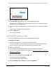

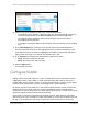
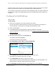
Table Of Contents
- 8-Port or 16-Port Gigabit Smart Managed Pro Switch with PoE+ and 2 SFP Ports
- Contents
- 1 Get Started
- Available publications
- Switch management and discovery overview
- Change the default IP address of the switch
- Discover or change the switch IP address
- About the user interfaces
- Access the local browser interface
- Change the language of the local browser interface
- Use the Device View of the local browser interface
- Interface naming conventions
- Configure interface settings
- Context–sensitive help and access to the support website
- Access the user manual online
- Register your product
- 2 Configure System Information
- View or define system information
- Configure the IP network settings for management access
- Configure the time settings
- Configure denial of service settings
- Configure the DNS settings
- Configure green Ethernet settings
- Use the Device View
- Configure Power over Ethernet
- Configure SNMP
- Configure LLDP
- Configure a DHCP L2 relay, DHCP snooping, and dynamic ARP inspection
- Set up PoE timer schedules
- 3 Configure Switching
- Configure the port settings
- Configure link aggregation groups
- Configure VLANs
- Configure a voice VLAN
- Configure Auto-VoIP
- Configure Spanning Tree Protocol
- Configure multicast
- Manage IGMP snooping
- Configure IGMP snooping
- Configure IGMP snooping for interfaces
- View, search, or clear the IGMP snooping table
- Configure IGMP snooping for VLANs
- Modify IGMP snooping settings for a VLAN
- Disable IGMP snooping on a VLAN and remove it from the table
- Configure one or more IGMP multicast router interfaces
- Configure an IGMP multicast router VLAN
- IGMP snooping querier overview
- Configure an IGMP snooping querier
- Configure an IGMP snooping querier for a VLAN
- Display the status of the IGMP snooping querier for VLANs
- Manage MLD snooping
- Enable MLD snooping
- Configure MLD snooping for interfaces
- Configure the MLD VLAN settings
- Modify the MLD snooping settings for a VLAN
- Remove MLD snooping from a VLAN
- Configure one or more MLD multicast router interfaces
- Configure an MLD multicast router VLAN
- Configure an MLD snooping querier
- Configure the MLD snooping querier VLAN settings
- Configure multicast VLAN registration
- View, search, and manage the MAC address table
- Configure Layer 2 loop protection
- 4 Configure Routing
- 5 Configure Quality of Service
- 6 Manage Device Security
- Change the device password for the local browser interface
- Manage the RADIUS settings
- Configure the TACACS+ settings
- Configure authentication lists
- Manage the Smart Control Center Utility
- Configure management access
- Control access with profiles and rules
- Configure port authentication
- Set up traffic control
- Configure access control lists
- Use the ACL Wizard to create a simple ACL
- Configure a MAC ACL
- Configure MAC ACL rules
- Configure MAC bindings
- View or delete MAC ACL bindings in the MAC binding table
- Configure a basic or extended IPv4 ACL
- Configure rules for a basic IPv4 ACL
- Configure rules for an extended IPv4 ACL
- Configure an IPv6 ACL
- Configure rules for an IPv6 ACL
- Configure IP ACL interface bindings
- View or delete IP ACL bindings in the IP ACL binding table
- Configure VLAN ACL bindings
- 7 Monitor the Switch and the Traffic
- 8 Maintain or Troubleshoot the Switch
- A Configuration Examples
- B Specifications and Default Settings

8-Port or 16-Port Gigabit Smart Managed Pro Switch Model GS418TPP, GS510TLP, and GS510TPP
Configure Switching User Manual133
The range is 1500 to 9198. The default maximum frame size is 1500.
15. From the Flow Control menu, select the configuration for IEEE 802.3 flow control.
• Disable. If the port buffers become full, the switch does not send pause frames, and
data loss could occur.
This is the default setting.
• Symmetric. If the port buffers become full, the switch sends pause frames to stop
traffic.
Flow control helps to prevent data loss when the port cannot keep up with the number
of frames being switched. When you enable flow control, the switch can send a pause
frame to stop traf
fic on the port if the amount of memory used by the packets on the
port exceeds a preconfigured threshold and responds to pause requests from partner
devices. The paused port does not forward packets for the time that is specified in the
pause frame. When the pause frame time elapses, or the utilization returns to a
specified low threshold, the switch enables the port to again transmit frames. The
switch also honors incoming pause frames by temporarily halting transmission.
• Asymmetric. If the port buf
fers become full, the switch does not send pause frames,
and data loss could occur. However
, the switch does honor incoming pause frames by
temporarily halting transmission.
Note: For LAG interfaces, flow control mode is displayed as a blank field
because flow control is not applicable.
16. Click the Apply button.
Your settings are saved.
The following table describes the nonconfigurable data that is displayed.
Table 30. Port Configuration information
Field Description
Port Type For normal ports this field is blank. Otherwise, the possible values are as
follows:
Physical Status The port speed and duplex mode.
Link Status Indicates whether the link is up or down.
MAC Address The physical address of the specified interface.
PortList Bit Offset The bit offset value that corresponds to the port when the MIB object type
PortList is used to manage in SNMP
.
ifIndex The ifIndex of the interface table entry associated with this port.
• Mirrored.
The port is a mirrored port on which all the traffic is copied
to the probe port.
• Probe
. Use this port to monitor a mirrored port.
• Trunk Member. The port is a member of a link aggregation trunk.
Look at the LAG pages for more information.