
User Manual


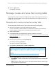


Table Of Contents
- 8-Port or 16-Port Gigabit Smart Managed Pro Switch with PoE+ and 2 SFP Ports
- Contents
- 1 Get Started
- Available publications
- Switch management and discovery overview
- Change the default IP address of the switch
- Discover or change the switch IP address
- About the user interfaces
- Access the local browser interface
- Change the language of the local browser interface
- Use the Device View of the local browser interface
- Interface naming conventions
- Configure interface settings
- Context–sensitive help and access to the support website
- Access the user manual online
- Register your product
- 2 Configure System Information
- View or define system information
- Configure the IP network settings for management access
- Configure the time settings
- Configure denial of service settings
- Configure the DNS settings
- Configure green Ethernet settings
- Use the Device View
- Configure Power over Ethernet
- Configure SNMP
- Configure LLDP
- Configure a DHCP L2 relay, DHCP snooping, and dynamic ARP inspection
- Set up PoE timer schedules
- 3 Configure Switching
- Configure the port settings
- Configure link aggregation groups
- Configure VLANs
- Configure a voice VLAN
- Configure Auto-VoIP
- Configure Spanning Tree Protocol
- Configure multicast
- Manage IGMP snooping
- Configure IGMP snooping
- Configure IGMP snooping for interfaces
- View, search, or clear the IGMP snooping table
- Configure IGMP snooping for VLANs
- Modify IGMP snooping settings for a VLAN
- Disable IGMP snooping on a VLAN and remove it from the table
- Configure one or more IGMP multicast router interfaces
- Configure an IGMP multicast router VLAN
- IGMP snooping querier overview
- Configure an IGMP snooping querier
- Configure an IGMP snooping querier for a VLAN
- Display the status of the IGMP snooping querier for VLANs
- Manage MLD snooping
- Enable MLD snooping
- Configure MLD snooping for interfaces
- Configure the MLD VLAN settings
- Modify the MLD snooping settings for a VLAN
- Remove MLD snooping from a VLAN
- Configure one or more MLD multicast router interfaces
- Configure an MLD multicast router VLAN
- Configure an MLD snooping querier
- Configure the MLD snooping querier VLAN settings
- Configure multicast VLAN registration
- View, search, and manage the MAC address table
- Configure Layer 2 loop protection
- 4 Configure Routing
- 5 Configure Quality of Service
- 6 Manage Device Security
- Change the device password for the local browser interface
- Manage the RADIUS settings
- Configure the TACACS+ settings
- Configure authentication lists
- Manage the Smart Control Center Utility
- Configure management access
- Control access with profiles and rules
- Configure port authentication
- Set up traffic control
- Configure access control lists
- Use the ACL Wizard to create a simple ACL
- Configure a MAC ACL
- Configure MAC ACL rules
- Configure MAC bindings
- View or delete MAC ACL bindings in the MAC binding table
- Configure a basic or extended IPv4 ACL
- Configure rules for a basic IPv4 ACL
- Configure rules for an extended IPv4 ACL
- Configure an IPv6 ACL
- Configure rules for an IPv6 ACL
- Configure IP ACL interface bindings
- View or delete IP ACL bindings in the IP ACL binding table
- Configure VLAN ACL bindings
- 7 Monitor the Switch and the Traffic
- 8 Maintain or Troubleshoot the Switch
- A Configuration Examples
- B Specifications and Default Settings

8-Port or 16-Port Gigabit Smart Managed Pro Switch Model GS418TPP, GS510TLP, and GS510TPP
Configure Routing User Manual247
Depending on the type of route that you are creating, specify the following information:
• In the Network Address field, specify the portion of the IP interface address that
identifies the attached network.
This is also referred to as the subnet/network mask.
• In the Next Hop IP Address field, specify the outgoing router IP address to use when
forwarding traf
fic to the next router (if any) in the path toward the destination.
The next router is always one of the adjacent neighbors or the IP address of the local
interface for a directly attached network.
• In the Preference field, specify the preference, which is an integer value from 1
to 255.
You can specify the preference value (sometimes called administrative distance) of
an individual static route. Among routes to the same destination, the route with the
lowest preference value is the route entered into the forwarding database. By
specifying the preference of a static route, you control whether a static route is more
or less preferred than routes from dynamic routing protocols. The preference also
controls whether a static route is more or less preferred than other static routes to the
same destination.
• In the Description field, enter a description for the route.
The description must consist of alphanumeric, hyphen, or underscore characters and
can be up to 31 characters in length.
7. Click the Add button.
The static route is added to the switch.
8. Click the Apply button.
Your settings are saved.
9. To refresh the page with the latest information about the switch, click the Update
button.
The following table describes the nonconfigurable data that is displayed.
Table 65. Learned Routes information
Field Description
Network Address The IP route prefix for the destination.
Subnet Mask The portion of the IP interface address that identifies the attached network (also referred
to as the subnet or network mask).
Protocol The protocol that created the specified route. The possibilities are one of the following:
• Local
• Static
Route Type The route type can be Connected, Static, or Dynamic, depending on the protocol.
Next Hop Interface The outgoing router interface to use when forwarding traffic to the destination.