
User Manual
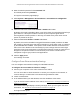
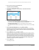
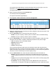
Table Of Contents
- S350 Series 8-Port Gigabit Ethernet Smart Switch
- Contents
- 1 Get Started
- Available Publications
- Switch Management and Discovery Overview
- Options to Change the Default IP Address of the Switch
- Discover or Change the Switch IP Address
- About the User Interfaces
- Access the Local Browser Interface
- Change the Language of the Local Browser Interface
- Use the Device View of the Local Browser Interface
- Interface Naming Conventions
- Configure Interface Settings
- Context-Sensitive Help and Access to the Support WebSite
- Access the User Guide Online
- Register Your Product
- 2 Configure System Information
- 3 Configure Switching
- Configure the Port Settings and Maximum Frame Size
- Configure Link Aggregation Groups
- Configure VLANs
- Configure a Voice VLAN
- Configure Auto-VoIP
- Configure Spanning Tree Protocol
- Configure Multicast
- View and Search the MFDB Table
- View the MFDB Statistics
- Configure the Auto-Video Multicast Settings
- About IGMP Snooping
- Configure IGMP Snooping
- Configure IGMP Snooping for Interfaces
- View, Search, or Clear the IGMP Snooping Table
- Configure IGMP Snooping for VLANs
- Modify IGMP Snooping Settings for a VLAN
- Disable IGMP Snooping on a VLAN
- Configure a Multicast Router Interface
- Configure a Multicast Router VLAN
- IGMP Snooping Querier Overview
- Configure an IGMP Snooping Querier
- Configure an IGMP Snooping Querier for VLANs
- Display IGMP Snooping Querier for VLAN Status
- View, Search, and Manage the MAC Address Table
- Configure Layer 2 Loop Protection
- 4 Configure Quality of Service
- 5 Manage Device Security
- Configure the Management Security Settings
- Configure Management Access
- Configure Port Authentication
- Set Up Traffic Control
- Configure Access Control Lists
- Use the ACL Wizard to Create a Simple ACL
- Configure a Basic MAC ACL
- Configure MAC ACL Rules
- Configure MAC Bindings
- View or Delete MAC ACL Bindings in the MAC Binding Table
- Configure a Basic or Extended IP ACL
- Configure Rules for a Basic IP ACL
- Configure Rules for an Extended IP ACL
- Configure IP ACL Interface Bindings
- View or Delete IP ACL Bindings in the IP ACL Binding Table
- Configure VLAN ACL Bindings
- 6 Monitor the System
- 7 Maintenance
- A Configuration Examples
- B Specifications and Default Settings

S350 Series 8-Port Gigabit Ethernet Smart Switch Models GS308T and GS310TP
Configure System Information User Manual66
the PD does not perform Layer 2 classification or if the switch performs
2-event Layer 1 classification.
• 802.3at.
The port is powered in the IEEE 802.3at mode and is backward compatible
with IEEE 802.3af. The 802.3at mode is the default mode. In this mode, if the switch
detects that the attached PD requests more power than IEEE 802.3af but is not an
IEEE 802.3at Class 4 device, the PD does not receive power from the switch.
10. From the Power Limit T
ype menu, select how the port controls the maximum power that it
can deliver:
• None.
The port draws up to Class 0 maximum power in low power mode and up to
Class 4 maximum power in high power mode.
• Class.
The port power limit is equal to the class of the attached PD.
• User.
The port power limit is equal to the value that is specified in the Power Limit
(mW) field. This is the default setting.
Note: If a PD does not report its class correctly, use of these options can
preserve additional PoE power by preventing the switch from
delivering more power than the PD requires. However, depending on
which option you select, a PD that does not report its class correctly
might not power up at all.
11. In the Power Limit (mW) field, enter the maximum power (in mW) that the port can deliver
.
The range is 3,000–30,000 mW. The default is 30,000 mW.
12. From the Detection T
ype menu, select how the port detects the attached PD:
• IEEE 802.
The port performs a 4-point resistive detection. This is the default setting.
• 4pt802.3af+legacy.
The port performs a 4-point resistive detection, and if required,
continues with legacy detection.
• Legacy.
The port performs legacy detection.
13. From the T
imer Schedule menu, select a timer schedule or select None, which is the
default selection.
For information about setting up and configuring PoE timer schedules, see
Set Up PoE
Timer Schedules on page 94.
14. Click the Apply button.
Your settings are saved.
The following table describes the nonconfigurable fields on the page.
Table 15. PoE Port Configuration
Field Description
High Power All ports supports high power mode.
Power Limit (mW) The maximum power in milliwatts that can be provided by the port.