
User Manual
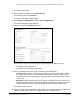
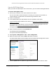
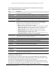
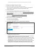
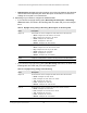
Table Of Contents
- S350 Series 8-Port Gigabit Ethernet Smart Switch
- Contents
- 1 Get Started
- Available Publications
- Switch Management and Discovery Overview
- Options to Change the Default IP Address of the Switch
- Discover or Change the Switch IP Address
- About the User Interfaces
- Access the Local Browser Interface
- Change the Language of the Local Browser Interface
- Use the Device View of the Local Browser Interface
- Interface Naming Conventions
- Configure Interface Settings
- Context-Sensitive Help and Access to the Support WebSite
- Access the User Guide Online
- Register Your Product
- 2 Configure System Information
- 3 Configure Switching
- Configure the Port Settings and Maximum Frame Size
- Configure Link Aggregation Groups
- Configure VLANs
- Configure a Voice VLAN
- Configure Auto-VoIP
- Configure Spanning Tree Protocol
- Configure Multicast
- View and Search the MFDB Table
- View the MFDB Statistics
- Configure the Auto-Video Multicast Settings
- About IGMP Snooping
- Configure IGMP Snooping
- Configure IGMP Snooping for Interfaces
- View, Search, or Clear the IGMP Snooping Table
- Configure IGMP Snooping for VLANs
- Modify IGMP Snooping Settings for a VLAN
- Disable IGMP Snooping on a VLAN
- Configure a Multicast Router Interface
- Configure a Multicast Router VLAN
- IGMP Snooping Querier Overview
- Configure an IGMP Snooping Querier
- Configure an IGMP Snooping Querier for VLANs
- Display IGMP Snooping Querier for VLAN Status
- View, Search, and Manage the MAC Address Table
- Configure Layer 2 Loop Protection
- 4 Configure Quality of Service
- 5 Manage Device Security
- Configure the Management Security Settings
- Configure Management Access
- Configure Port Authentication
- Set Up Traffic Control
- Configure Access Control Lists
- Use the ACL Wizard to Create a Simple ACL
- Configure a Basic MAC ACL
- Configure MAC ACL Rules
- Configure MAC Bindings
- View or Delete MAC ACL Bindings in the MAC Binding Table
- Configure a Basic or Extended IP ACL
- Configure Rules for a Basic IP ACL
- Configure Rules for an Extended IP ACL
- Configure IP ACL Interface Bindings
- View or Delete IP ACL Bindings in the IP ACL Binding Table
- Configure VLAN ACL Bindings
- 6 Monitor the System
- 7 Maintenance
- A Configuration Examples
- B Specifications and Default Settings

S350 Series 8-Port Gigabit Ethernet Smart Switch Models GS308T and GS310TP
Configure System Information User Manual46
4. Enter the switch’s password in the Password field.
The default password is password.
The System Information page displays.
5. Select System > Management > T
ime > SNTP Server Configuration.
The SNTP Server Configuration page displays.
6. From the Server T
ype menu, select the type of SNTP address to enter in the address field.
The address can be either an IP address (IPv4) or a host name (DNS).
7. In the Address field, specify the IP address or the host name of the SNTP server
.
This is a text string of up to 64 characters, containing the encoded unicast IP address or
host name of an SNTP server
. Unicast SNTP requests are sent to this address. If this
address is a DNS host name, then that host name is resolved into an IP address each
time an SNTP request is sent to it.
8. If the UDP port on the SNTP server to which SNTP requests are sent is not the standard
port (123), specify the port number in the Port field.
The range is from 1 to 65535. The default value is 123.
9. In the Priority field, specify the priority order which to query the servers.
The SNTP client on the device continues sending SNTP requests to different servers until
a successful response is received, or all servers are exhausted.
The priority indicates the
order in which to query the servers. The request is sent to an SNTP server with a priority
value of 1 first, then to a server with a priority value of 2, and so on. If any servers are
assigned the same priority, the SNTP client contacts the servers in the order that they
appear in the table. The range is from 1 to 3. The default value is 1.
10. In the V
ersion field, specify the NTP version running on the server.
The range is 1 to 4. The default value is 4.
11. Click the Add button.
The SNTP server entry is added.
12. Repeat the previous steps to add additional SNTP servers.
You can configure up to three SNTP servers.