
User Manual
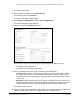
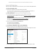
Table Of Contents
- S350 Series 8-Port Gigabit Ethernet Smart Switch
- Contents
- 1 Get Started
- Available Publications
- Switch Management and Discovery Overview
- Options to Change the Default IP Address of the Switch
- Discover or Change the Switch IP Address
- About the User Interfaces
- Access the Local Browser Interface
- Change the Language of the Local Browser Interface
- Use the Device View of the Local Browser Interface
- Interface Naming Conventions
- Configure Interface Settings
- Context-Sensitive Help and Access to the Support WebSite
- Access the User Guide Online
- Register Your Product
- 2 Configure System Information
- 3 Configure Switching
- Configure the Port Settings and Maximum Frame Size
- Configure Link Aggregation Groups
- Configure VLANs
- Configure a Voice VLAN
- Configure Auto-VoIP
- Configure Spanning Tree Protocol
- Configure Multicast
- View and Search the MFDB Table
- View the MFDB Statistics
- Configure the Auto-Video Multicast Settings
- About IGMP Snooping
- Configure IGMP Snooping
- Configure IGMP Snooping for Interfaces
- View, Search, or Clear the IGMP Snooping Table
- Configure IGMP Snooping for VLANs
- Modify IGMP Snooping Settings for a VLAN
- Disable IGMP Snooping on a VLAN
- Configure a Multicast Router Interface
- Configure a Multicast Router VLAN
- IGMP Snooping Querier Overview
- Configure an IGMP Snooping Querier
- Configure an IGMP Snooping Querier for VLANs
- Display IGMP Snooping Querier for VLAN Status
- View, Search, and Manage the MAC Address Table
- Configure Layer 2 Loop Protection
- 4 Configure Quality of Service
- 5 Manage Device Security
- Configure the Management Security Settings
- Configure Management Access
- Configure Port Authentication
- Set Up Traffic Control
- Configure Access Control Lists
- Use the ACL Wizard to Create a Simple ACL
- Configure a Basic MAC ACL
- Configure MAC ACL Rules
- Configure MAC Bindings
- View or Delete MAC ACL Bindings in the MAC Binding Table
- Configure a Basic or Extended IP ACL
- Configure Rules for a Basic IP ACL
- Configure Rules for an Extended IP ACL
- Configure IP ACL Interface Bindings
- View or Delete IP ACL Bindings in the IP ACL Binding Table
- Configure VLAN ACL Bindings
- 6 Monitor the System
- 7 Maintenance
- A Configuration Examples
- B Specifications and Default Settings

S350 Series 8-Port Gigabit Ethernet Smart Switch Models GS308T and GS310TP
Configure System Information User Manual45
The following is an example of strata:
• Stratum 0. A real-time clock is used as the time source, for example, a GPS system.
• Stratum 1. A server that is directly linked to a Stratum 0 time source is used. Stratum 1
time servers provide primary network time standards.
• Stratum 2.
The time source is distanced from the Stratum 1 server over a network path.
For example, a Stratum 2 server receives the time over a network link, through NTP, from
a Stratum 1 server.
Information received from SNTP servers is evaluated based on the time level and server
type.
SNTP time definitions are assessed and determined by the following time levels:
•T1. Time that the original request was sent by the client.
•T2.
Time that the original request was received by the server.
•T3.
Time that the server sent a reply.
•T4.
Time that the client received the server's reply.
The device can poll unicast server types for the server time.
Polling for unicast information is used for polling a server for which the IP address is known.
SNTP servers that were configured on the device are the only ones that are polled for
synchronization information.
T1 through T4 are used to determine server time. This is the
preferred method for synchronizing device time because it is the most secure method. If this
method is selected, SNTP information is accepted only from SNTP servers defined on the
device using the SNTP Server Configuration page.
The device retrieves synchronization information, either by actively requesting information or
at every poll interval.
You can view and modify information for adding and modifying Simple Network Time
Protocol SNTP servers.
Add an SNTP Server
To add an SNTP server:
1. Connect your computer to the same network as the switch.
You can use a WiFi or wired connection to connect your computer to the network, or
connect directly to a switch that is of
f-network using an Ethernet cable.
2. Launch a web browser.
3. In the address field of your web browser
, enter the IP address of the switch.
If you do not know the IP address of the switch, see
Discover or Change the Switch IP
Address on page 12.
Your web browser might display a security message, which you can ignore. For more
information, see Access the Local Browser Interface on page 18.
The login window opens.