
User Manual
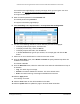


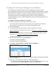
Table Of Contents
- S350 Series 8-Port Gigabit Ethernet Smart Switch
- Contents
- 1 Get Started
- Available Publications
- Switch Management and Discovery Overview
- Options to Change the Default IP Address of the Switch
- Discover or Change the Switch IP Address
- About the User Interfaces
- Access the Local Browser Interface
- Change the Language of the Local Browser Interface
- Use the Device View of the Local Browser Interface
- Interface Naming Conventions
- Configure Interface Settings
- Context-Sensitive Help and Access to the Support WebSite
- Access the User Guide Online
- Register Your Product
- 2 Configure System Information
- 3 Configure Switching
- Configure the Port Settings and Maximum Frame Size
- Configure Link Aggregation Groups
- Configure VLANs
- Configure a Voice VLAN
- Configure Auto-VoIP
- Configure Spanning Tree Protocol
- Configure Multicast
- View and Search the MFDB Table
- View the MFDB Statistics
- Configure the Auto-Video Multicast Settings
- About IGMP Snooping
- Configure IGMP Snooping
- Configure IGMP Snooping for Interfaces
- View, Search, or Clear the IGMP Snooping Table
- Configure IGMP Snooping for VLANs
- Modify IGMP Snooping Settings for a VLAN
- Disable IGMP Snooping on a VLAN
- Configure a Multicast Router Interface
- Configure a Multicast Router VLAN
- IGMP Snooping Querier Overview
- Configure an IGMP Snooping Querier
- Configure an IGMP Snooping Querier for VLANs
- Display IGMP Snooping Querier for VLAN Status
- View, Search, and Manage the MAC Address Table
- Configure Layer 2 Loop Protection
- 4 Configure Quality of Service
- 5 Manage Device Security
- Configure the Management Security Settings
- Configure Management Access
- Configure Port Authentication
- Set Up Traffic Control
- Configure Access Control Lists
- Use the ACL Wizard to Create a Simple ACL
- Configure a Basic MAC ACL
- Configure MAC ACL Rules
- Configure MAC Bindings
- View or Delete MAC ACL Bindings in the MAC Binding Table
- Configure a Basic or Extended IP ACL
- Configure Rules for a Basic IP ACL
- Configure Rules for an Extended IP ACL
- Configure IP ACL Interface Bindings
- View or Delete IP ACL Bindings in the IP ACL Binding Table
- Configure VLAN ACL Bindings
- 6 Monitor the System
- 7 Maintenance
- A Configuration Examples
- B Specifications and Default Settings

S350 Series 8-Port Gigabit Ethernet Smart Switch Models GS308T and GS310TP
Configure Quality of Service User Manual177
6. Click the LAG link to display all LAG interfaces or click the All link to display both all physical
and all LAG interfaces.
7. Select one or more interfaces by taking one of the following actions:
• To configure a single interface, select the check box associated with the port, or type
the port number in the
Go To Interface field and click the Go button.
• To configure multiple interfaces with the same settings, select the check box
associated with each interface.
• To configure all interfaces with the same settings, select the check box in the heading
row
.
8. From the Interface Trust Mode menu, select one of the following trust mode options for
ingress traf
fic on the selected interfaces:
• Untrusted. Do not trust any CoS packet marking at ingress.
• 802.1p. The eight priority tags that are specified in IEEE 802.1p are p0 to p7.
The
QoS setting lets you map each of the eight priority levels to one of seven internal
hardware priority queues. The default value is 802.1p.
• DSCP. The six most significant bits of the DiffServ field are called the Differentiated
Services Code Point (DSCP) bits.
9. In the
Interface Shaping Rate field, specify the maximum egress bandwidth allowed.
This setting is used to shape the outbound transmission rate in increments of 1 percent in
a range of 0–100. This value is controlled independently of any per-queue maximum
bandwidth configuration. It is ef
fectively a second-level shaping mechanism. The default
value is 0. The value 0 means that the maximum is unlimited.
10. In the Interface Ingress Rate Limit field, specify the maximum ingress bandwidth allowed.
This setting is used to shape the inbound transmission rate in increments of 1 percent in
a range of 0–100. The interface discards traf
fic that arrives at a bandwidth in excess of
the specified limit.
11. Click the Apply button.
Your settings are saved.