
User Manual
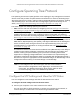
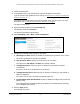

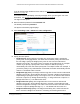
Table Of Contents
- S350 Series 8-Port Gigabit Ethernet Smart Switch
- Contents
- 1 Get Started
- Available Publications
- Switch Management and Discovery Overview
- Options to Change the Default IP Address of the Switch
- Discover or Change the Switch IP Address
- About the User Interfaces
- Access the Local Browser Interface
- Change the Language of the Local Browser Interface
- Use the Device View of the Local Browser Interface
- Interface Naming Conventions
- Configure Interface Settings
- Context-Sensitive Help and Access to the Support WebSite
- Access the User Guide Online
- Register Your Product
- 2 Configure System Information
- 3 Configure Switching
- Configure the Port Settings and Maximum Frame Size
- Configure Link Aggregation Groups
- Configure VLANs
- Configure a Voice VLAN
- Configure Auto-VoIP
- Configure Spanning Tree Protocol
- Configure Multicast
- View and Search the MFDB Table
- View the MFDB Statistics
- Configure the Auto-Video Multicast Settings
- About IGMP Snooping
- Configure IGMP Snooping
- Configure IGMP Snooping for Interfaces
- View, Search, or Clear the IGMP Snooping Table
- Configure IGMP Snooping for VLANs
- Modify IGMP Snooping Settings for a VLAN
- Disable IGMP Snooping on a VLAN
- Configure a Multicast Router Interface
- Configure a Multicast Router VLAN
- IGMP Snooping Querier Overview
- Configure an IGMP Snooping Querier
- Configure an IGMP Snooping Querier for VLANs
- Display IGMP Snooping Querier for VLAN Status
- View, Search, and Manage the MAC Address Table
- Configure Layer 2 Loop Protection
- 4 Configure Quality of Service
- 5 Manage Device Security
- Configure the Management Security Settings
- Configure Management Access
- Configure Port Authentication
- Set Up Traffic Control
- Configure Access Control Lists
- Use the ACL Wizard to Create a Simple ACL
- Configure a Basic MAC ACL
- Configure MAC ACL Rules
- Configure MAC Bindings
- View or Delete MAC ACL Bindings in the MAC Binding Table
- Configure a Basic or Extended IP ACL
- Configure Rules for a Basic IP ACL
- Configure Rules for an Extended IP ACL
- Configure IP ACL Interface Bindings
- View or Delete IP ACL Bindings in the IP ACL Binding Table
- Configure VLAN ACL Bindings
- 6 Monitor the System
- 7 Maintenance
- A Configuration Examples
- B Specifications and Default Settings

S350 Series 8-Port Gigabit Ethernet Smart Switch Models GS308T and GS310TP
Configure Switching User Manual133
Configure Spanning Tree Protocol
The Spanning Tree Protocol (STP) provides a tree topology for any arrangement of network
devices. STP also provides one path between end stations on a network, eliminating loops.
STP (also referred to as “classic” STP) provides a single path between end stations, avoiding
and eliminating loops. For information about configuring the global STP settings for the
switch, see
Configure the STP Settings and View the STP Status on page 133.
The switch support the following spanning tree versions:
• CST. Common STP
. For information on configuring CST, see Configure and View the
CST Settings on page 135 and Configure and View the CST Port Settings on page 137.
• MSTP. Multiple Spanning
Tree Protocol (MSTP, also referred to as MST) supports
multiple instances of spanning tree to efficiently channel VLAN traffic over different
interfaces. For information on configuring MSTP, see
Manage MST Settings on page 142
and
Configure and View the Port Settings for an MST Instance on page 144.
• RSTP. Rapid STP
. Each instance of the spanning tree behaves in the manner specified in
IEEE 802.1w, Rapid Spanning Tree (RSTP), with slight modifications in the working but
not the end effect (chief among the effects is the rapid transitioning of the port to the
forwarding state). For information on viewing the RSTP state, see
View Rapid STP
Information on page 141.
The difference between the RSTP and the traditional STP (IEEE 802.1D) is the ability to
configure and recognize full-duplex connectivity and ports that are connected to end
stations, resulting in rapid transitioning of the port to the forwarding state and the
suppression of
Topology Change Notification. These features are represented by the
parameters pointtopoint and edgeport. MSTP is compatible with both RSTP and STP. It
behaves in a way that is appropriate for STP and RSTP bridges. An MSTP bridge can be
configured to behave entirely as an RSTP bridge or an STP bridge.
Note: For two bridges to be in the same region, the force version must be
802.1s and their configuration names, digest keys, and revision levels
must match. For additional information about regions and their effect
on network topology, refer to the IEEE 802.1Q standard.
Configure the STP Settings and View the STP Status
You can configure the STP settings and view the STP status on the switch.
To configure the STP settings and view the STP status:
1. Connect your computer to the same network as the switch.
You can use a WiFi or wired connection to connect your computer to the network, or
connect directly to a switch that is of
f-network using an Ethernet cable.