
User Manual
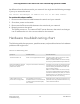
Table Of Contents
- Contents
- 1. Hardware Overview of the Switch
- 2. Install and Access the Switch in Your Network
- 3. Use VLANS for Traffic Segmentation
- VLAN overview
- Create basic port-based VLANs
- Assign ports to multiple port-based VLANs
- Create 802.1Q-based VLANs in a basic configuration
- Create 802.1Q-based VLANs in an advanced configuration
- Add tagged or untagged ports to an 802.1Q-based VLAN
- Specify a port PVID for an 802.1Q-based VLAN
- Manage the voice VLAN
- 4. Optimize Performance With Quality of Service
- 5. Manage Network Settings
- 6. Manage and Monitor the Switch
- Manage flow control
- Manage the port speed and the port status
- Enable loop prevention
- Manage the power saving mode
- Manually download and upgrade the firmware
- Reboot the switch
- Save the switch configuration
- Restore a saved switch configuration
- Return the switch to its factory default settings
- Enable port mirroring
- View switch information or change the switch device name
- View or clear the port statistics
- 7. Diagnostics and Troubleshooting
- A. Factory Default Settings and Technical Specifications
- B. Mount the Switch

be different from the subnet used in your network. You might see the following message
if you try to access the switch:
The switch and manager IP address are not in the same subnet.
To resolve this subnet conflict:
1. Disconnect the Ethernet cable between the switch and your network.
2. Shut down power to the switch.
3. Reconnect the Ethernet cable between the switch and your network.
4. Reapply power to the switch.
The switch powers on. The network DHCP server discovers the switch and assigns
it an IP address that is in the correct subnet for the network.
Hardware troubleshooting chart
The following table lists symptoms, possible causes, and possible solutions for hardware
problems that might occur.
Table 5. Troubleshooting chart
Possible SolutionPossible CauseSymptom
Check the power cable connections at the
switch and the power source.
Make sure that all cables are used correctly
and comply with the Ethernet specifications.
Power is not supplied to the switch.The Power LED is off.
Check the crimp on the connectors and make
sure that the plug is properly inserted and
locked into the port at both the switch and
the connecting device.
Make sure that all cables are used correctly
and comply with the Ethernet specifications.
Check for a defective port, cable, or module
by testing them in an alternate environment
where all products are functioning.
The port connection is not working.Both ports LEDs are off when
the port is connected to a
powered-on device.
Break the loop by making sure that only one
path exists from any networked device to any
other networked device.
One possible cause is that a
broadcast storm occurred and that
a network loop (redundant path)
was created.
A file transfer is slow or
performance is degraded.
User Manual70Diagnostics and
Troubleshooting
8-Port Gigabit Ethernet Plus Switch with 2-Port 10G/Multi-Gig Uplinks GS110EMX