
User Manual
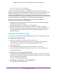
Table Of Contents
- Insight Managed 28-Port and 52-Port Gigabit Ethernet Smart Cloud Switches with 2 SFP 1G & 2 SFP+ 10G Fiber Ports
- Contents
- 1. Getting Started
- Switch Management Options and Default Management Mode
- Available Publications
- Web Browser Requirements and Supported Browsers
- User-Defined Fields
- Interface Naming Conventions
- Access the Switch
- Change the Management Mode of the Switch
- Register the Switch
- How to Configure Interface Settings
- Local Browser Interface Device View
- 2. Configure System Information
- View and Configure the Switch Management Settings
- View or Define System Information
- View the Switch CPU Status
- Configure the CPU Thresholds
- Configure the IPv4 Address for the Network Interface and Management VLAN
- Configure the IPv6 Address for the Network Interface
- View the IPv6 Network Neighbor
- Configure the Time Settings
- Configure Denial of Service Settings
- Configure DNS Settings
- Configure Green Ethernet Settings
- Manage the Bonjour Settings and View Bonjour Information
- Control the LEDs
- Use the Device View
- Configure Power over Ethernet
- Configure SNMP
- Configure Link Layer Discovery Protocol
- Configure DHCP L2 Relay and DHCP Snooping
- Set Up PoE Timer Schedules
- View and Configure the Switch Management Settings
- 3. Configure Switching
- 4. Configuring Routing
- 5. Configure Quality of Service
- 6. Manage Device Security
- Management Security Settings
- Configure Management Access
- Configure Port Authentication
- Set Up Traffic Control
- Configure Access Control Lists
- Use the ACL Wizard to Create a Simple ACL
- Configure a Basic MAC ACL
- Configure MAC ACL Rules
- Configure MAC Bindings
- View or Delete MAC ACL Bindings in the MAC Binding Table
- Configure an IP ACL
- Configure Rules for a Basic IP ACL
- Configure Rules for an Extended IP ACL
- Configure an IPv6 ACL
- Configure Rules for an IPv6 ACL
- Configure IP ACL Interface Bindings
- View or Delete IP ACL Bindings in the IP ACL Binding Table
- Configure VLAN ACL Bindings
- 7. Perform Maintenance Tasks
- 8. Manage Power over Ethernet
- 9. Monitor the System
- A. Configuration Examples
- B. Hardware Specifications and Default Values

Configure System Information
72
Insight Managed 28-Port and 52-Port Gigabit Ethernet Smart Cloud Switches
Configure the SNMPv1/v2 Community
Only the communities that you define can access to the switch using the SNMP V1 and
SNMP V2 protocols. Only those communities with read/write level access can be used to
change the configuration using SNMP.
Add an SNMP Community:
To add an SNMP community:
1. Connect your computer to the same network as the switch.
You can use a WiFi or wired connection to connect your computer to the network, or
connect directly to a switch that is off-network using an Ethernet cable.
2. Launch a web browser.
3. In the address field of your web browser, enter the IP address of the switch.
If you do not know the IP address of the switch, see Access the Switch on page 13.
The login window opens.
4. Enter the switch’s password in the password field.
The default password is password. If you added the switch to a network on the Insight
app before and you did not yet change the password through the local browser interface,
enter your Insight network password.
The System Information page displays.
5. Select System > SNMP > SNMPv1/v2 > Community Configuration.
The Community Configuration page displays.
6. In the Management Station IP field, specify the IP address of the management station.
7. In the Management Station IP Mask field, specify the subnet mask to associate with the
management station IP address.
Together, the management station IP address and the management station IP mask
denote a range of IP addresses from which SNMP clients can use the community to
access this device. If either the management station IP address or management station
IP mask value is 0.0.0.0, access is allowed from any IP address. Otherwise, each client’s
address is ANDed with the mask, as is the management station IP address. If the values
are equal, access is allowed. For example, if the management station IP address is
192.168.1.0 and the management station IP mask is 255.255.255.0, any client whose
address is in the 192.168.1.0–192.168.1.255 range is allowed access.
To allow access from only one station, use that station’s IP address as the management
station IP address and use a management station IP mask value of 255.255.255.255.
8. In the Community String field, specify a community name.
9. From the Access Mode menu, select the access level for this community, which is either
Read/Write or Read Only.
10. From the Status menu, select to enable or disable the community.