
User Manual
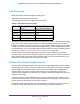
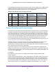
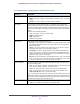
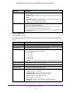
Table Of Contents
- Insight Managed 28-Port and 52-Port Gigabit Ethernet Smart Cloud Switches with 2 SFP 1G & 2 SFP+ 10G Fiber Ports
- Contents
- 1. Getting Started
- Switch Management Options and Default Management Mode
- Available Publications
- Web Browser Requirements and Supported Browsers
- User-Defined Fields
- Interface Naming Conventions
- Access the Switch
- Change the Management Mode of the Switch
- Register the Switch
- How to Configure Interface Settings
- Local Browser Interface Device View
- 2. Configure System Information
- View and Configure the Switch Management Settings
- View or Define System Information
- View the Switch CPU Status
- Configure the CPU Thresholds
- Configure the IPv4 Address for the Network Interface and Management VLAN
- Configure the IPv6 Address for the Network Interface
- View the IPv6 Network Neighbor
- Configure the Time Settings
- Configure Denial of Service Settings
- Configure DNS Settings
- Configure Green Ethernet Settings
- Manage the Bonjour Settings and View Bonjour Information
- Control the LEDs
- Use the Device View
- Configure Power over Ethernet
- Configure SNMP
- Configure Link Layer Discovery Protocol
- Configure DHCP L2 Relay and DHCP Snooping
- Set Up PoE Timer Schedules
- View and Configure the Switch Management Settings
- 3. Configure Switching
- 4. Configuring Routing
- 5. Configure Quality of Service
- 6. Manage Device Security
- Management Security Settings
- Configure Management Access
- Configure Port Authentication
- Set Up Traffic Control
- Configure Access Control Lists
- Use the ACL Wizard to Create a Simple ACL
- Configure a Basic MAC ACL
- Configure MAC ACL Rules
- Configure MAC Bindings
- View or Delete MAC ACL Bindings in the MAC Binding Table
- Configure an IP ACL
- Configure Rules for a Basic IP ACL
- Configure Rules for an Extended IP ACL
- Configure an IPv6 ACL
- Configure Rules for an IPv6 ACL
- Configure IP ACL Interface Bindings
- View or Delete IP ACL Bindings in the IP ACL Binding Table
- Configure VLAN ACL Bindings
- 7. Perform Maintenance Tasks
- 8. Manage Power over Ethernet
- 9. Monitor the System
- A. Configuration Examples
- B. Hardware Specifications and Default Values

Manage Power over Ethernet
364
Insight Managed 28-Port and 52-Port Gigabit Ethernet Smart Cloud Switches
PoE Overview
Model GC728XP includes 24 PoE plus (PoE+) ports.
Model GC752XP includes 48 PoE+ ports
The following table shows the capacity for each model.
By default, supplied power is prioritized in ascending port order, up to the total power budget
of the device. If the power requirements for the attached devices exceed the total power
budget of the switch, the power to the device on the highest-numbered PoE+ port is disabled
to make sure that the devices connected to the higher-priority, lower-numbered PoE+ ports
are supported first. You can manually change the prioritization scheme by changing the port
priority (see Manage and View the PoE+ Port Configuration on page 368).
It is important to note that although a device is listed as an 802.3at (PoE+) powered or
802.3af (PoE) powered device, it might not require the maximum power limit that is specified.
Many devices require less power, allowing all PoE ports to be active simultaneously, when
the devices correctly report their PoE class to the switch.
Device Class Power Requirements
PoE and PoE+ use Ethernet cables to supply power to PoE-capable devices on the network,
such as WiFi access points, IP cameras, VoIP phones, and switches. The switch is compliant
with the IEEE 802.3at standard (PoE+) and backward compatible with the IEEE 802.3af
standard (PoE). The switch can pass power through to any powered device (PD) that
supports these standards. PoE and PoE+ let you power such devices without the need for a
separate power supply.
The switch supports a Plug-and-Play process by which it detects the type of device that is
connected to one of its PoE+ ports and whether that device needs power and how much so
that the switch can provide the correct power the device.
During the Plug-and-Play process, the connected device can provide its Class response to
the switch in many ways, depending on how the vendor programmed the device.
Table 83. PoE capacities for each model
Model Maximum PoE Power
Per Port
Maximum Power Budget
Across All Active PoE Ports
GC728X PoE is not supported PoE is not supported
GC728XP 30W PoE+ (IEEE 802.3at) 390W
GC752X PoE is not supported PoE is not supported
GC752XP 30W PoE+ (IEEE 802.3at) 505W