
User Manual
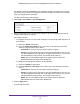
Table Of Contents
- Insight Managed 28-Port and 52-Port Gigabit Ethernet Smart Cloud Switches with 2 SFP 1G & 2 SFP+ 10G Fiber Ports
- Contents
- 1. Getting Started
- Switch Management Options and Default Management Mode
- Available Publications
- Web Browser Requirements and Supported Browsers
- User-Defined Fields
- Interface Naming Conventions
- Access the Switch
- Change the Management Mode of the Switch
- Register the Switch
- How to Configure Interface Settings
- Local Browser Interface Device View
- 2. Configure System Information
- View and Configure the Switch Management Settings
- View or Define System Information
- View the Switch CPU Status
- Configure the CPU Thresholds
- Configure the IPv4 Address for the Network Interface and Management VLAN
- Configure the IPv6 Address for the Network Interface
- View the IPv6 Network Neighbor
- Configure the Time Settings
- Configure Denial of Service Settings
- Configure DNS Settings
- Configure Green Ethernet Settings
- Manage the Bonjour Settings and View Bonjour Information
- Control the LEDs
- Use the Device View
- Configure Power over Ethernet
- Configure SNMP
- Configure Link Layer Discovery Protocol
- Configure DHCP L2 Relay and DHCP Snooping
- Set Up PoE Timer Schedules
- View and Configure the Switch Management Settings
- 3. Configure Switching
- 4. Configuring Routing
- 5. Configure Quality of Service
- 6. Manage Device Security
- Management Security Settings
- Configure Management Access
- Configure Port Authentication
- Set Up Traffic Control
- Configure Access Control Lists
- Use the ACL Wizard to Create a Simple ACL
- Configure a Basic MAC ACL
- Configure MAC ACL Rules
- Configure MAC Bindings
- View or Delete MAC ACL Bindings in the MAC Binding Table
- Configure an IP ACL
- Configure Rules for a Basic IP ACL
- Configure Rules for an Extended IP ACL
- Configure an IPv6 ACL
- Configure Rules for an IPv6 ACL
- Configure IP ACL Interface Bindings
- View or Delete IP ACL Bindings in the IP ACL Binding Table
- Configure VLAN ACL Bindings
- 7. Perform Maintenance Tasks
- 8. Manage Power over Ethernet
- 9. Monitor the System
- A. Configuration Examples
- B. Hardware Specifications and Default Values

Configuring Routing
212
Insight Managed 28-Port and 52-Port Gigabit Ethernet Smart Cloud Switches
Delete Routes
To delete one or more static routes:
1. Connect your computer to the same network as the switch.
You can use a WiFi or wired connection to connect your computer to the network, or
connect directly to a switch that is off-network using an Ethernet cable.
2. Launch a web browser.
3. In the address field of your web browser, enter the IP address of the switch.
If you do not know the IP address of the switch, see Access the Switch on page 13.
The login window opens.
4. Enter the switch’s password in the password field.
The default password is password. If you added the switch to a network on the Insight
app before and you did not yet change the password through the local browser interface,
enter your Insight network password.
The System Information page displays.
5. Select Routing > Routing Table > Route Configuration.
The Configure Routes page displays. The page also shows the Route Status section.
6. Select the check box next to each route to remove.
7. Click the Delete button.
The static route is deleted.
Configure ARP
The address resolution protocol (ARP) associates a layer 2 MAC address with a layer 3 IPv4
address. The switch support both dynamic and manual ARP configuration. With manual ARP
configuration, you can statically add entries into the ARP table.
ARP is a required part of the Internet protocol (IP) and is used to translate an IP address to a
media (MAC) address, defined by a local area network (LAN) such as an Ethernet network.
A device that must send an IP packet must learn the MAC address of the IP destination, or if
the destination is not on the same subnet, of the next hop router. The device achieves this by
broadcasting an ARP request packet, to which the intended recipient responds by sending an
ARP unicast reply that contains its MAC address. Once learned, the MAC address is used in
the destination address field of the Layer 2 header prepended to the IP packet.
The ARP cache is a table maintained locally in each device on the network. ARP cache
entries are learned by examining the source information in the ARP packet payload fields,
regardless of whether it is an ARP request or response. In this way, when an ARP request is
broadcast to all stations on a LAN segment or virtual LAN (VLAN), each recipient can store
the sender’s IP address and MAC address in its ARP cache. The ARP response, which is a
unicast reply, is normally detected only by the device that sends the ARP request. That