
User Manual
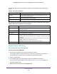

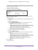
Table Of Contents
- Insight Managed 28-Port and 52-Port Gigabit Ethernet Smart Cloud Switches with 2 SFP 1G & 2 SFP+ 10G Fiber Ports
- Contents
- 1. Getting Started
- Switch Management Options and Default Management Mode
- Available Publications
- Web Browser Requirements and Supported Browsers
- User-Defined Fields
- Interface Naming Conventions
- Access the Switch
- Change the Management Mode of the Switch
- Register the Switch
- How to Configure Interface Settings
- Local Browser Interface Device View
- 2. Configure System Information
- View and Configure the Switch Management Settings
- View or Define System Information
- View the Switch CPU Status
- Configure the CPU Thresholds
- Configure the IPv4 Address for the Network Interface and Management VLAN
- Configure the IPv6 Address for the Network Interface
- View the IPv6 Network Neighbor
- Configure the Time Settings
- Configure Denial of Service Settings
- Configure DNS Settings
- Configure Green Ethernet Settings
- Manage the Bonjour Settings and View Bonjour Information
- Control the LEDs
- Use the Device View
- Configure Power over Ethernet
- Configure SNMP
- Configure Link Layer Discovery Protocol
- Configure DHCP L2 Relay and DHCP Snooping
- Set Up PoE Timer Schedules
- View and Configure the Switch Management Settings
- 3. Configure Switching
- 4. Configuring Routing
- 5. Configure Quality of Service
- 6. Manage Device Security
- Management Security Settings
- Configure Management Access
- Configure Port Authentication
- Set Up Traffic Control
- Configure Access Control Lists
- Use the ACL Wizard to Create a Simple ACL
- Configure a Basic MAC ACL
- Configure MAC ACL Rules
- Configure MAC Bindings
- View or Delete MAC ACL Bindings in the MAC Binding Table
- Configure an IP ACL
- Configure Rules for a Basic IP ACL
- Configure Rules for an Extended IP ACL
- Configure an IPv6 ACL
- Configure Rules for an IPv6 ACL
- Configure IP ACL Interface Bindings
- View or Delete IP ACL Bindings in the IP ACL Binding Table
- Configure VLAN ACL Bindings
- 7. Perform Maintenance Tasks
- 8. Manage Power over Ethernet
- 9. Monitor the System
- A. Configuration Examples
- B. Hardware Specifications and Default Values

Configuring Routing
211
Insight Managed 28-Port and 52-Port Gigabit Ethernet Smart Cloud Switches
8. For a static route only, in the Subnet Mask field, specify the subnet mask.
Also referred to as the network mask, the mask indicates the portion of the IP address
that identifies the attached network.
9. In the Next Hop IP Address field, specify the next hop IP address.
This is the outgoing router IP address to use when forwarding traffic to the next router (if
any) in the path towards the destination. The next router is always one of the adjacent
neighbors or the IP address of the local interface for a directly attached network. When
creating a route, the next hop IP must be on the same network as the routing interface.
Valid next hop IP addresses are listed in the Route Status table.
10. In the Preference field, specify the preference value for the route.
Among routes to the same destination, the route with the lowest preference value is the
route entered into the forwarding database. By specifying the preference of a static route,
you can control whether a static route is more preferred or less preferred. The preference
also controls whether a static route is more preferred or less preferred than other static
routes to the same destination.
11. As an option, in the Description field, specify a description to help identify the route.
12. Click the Add button.
The route is added.
The Route Status table provides information about the static routes that you manually
configured on the switch and the routes the switch learned dynamically.
Table 58. Routing table information
Field Description
Network Address The IP route prefix for the destination.
Subnet Mask Also referred to as the network mask, the portion of the IP interface address that
identifies the attached network.
Protocol The protocol that created the route. The protocol can be Local or Static.
Route Type Based on the protocol, Connected, Static, or Dynamic.
Next Hop Interface The outgoing router interface that must be used when the switch forwards traffic
to the destination.
Next Hop IP Address The outgoing router IP address that must be used when the switch forwards
traffic to the next router (if any) in the path towards the destination. The next
router is always one of the adjacent neighbors or the IP address of the local
interface for a directly attached network.
Preference A value from 1 to 255.
Metric The administrative cost of the path to the destination.