
User Manual
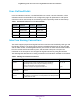
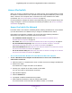
Table Of Contents
- Insight Managed 28-Port and 52-Port Gigabit Ethernet Smart Cloud Switches with 2 SFP 1G & 2 SFP+ 10G Fiber Ports
- Contents
- 1. Getting Started
- Switch Management Options and Default Management Mode
- Available Publications
- Web Browser Requirements and Supported Browsers
- User-Defined Fields
- Interface Naming Conventions
- Access the Switch
- Change the Management Mode of the Switch
- Register the Switch
- How to Configure Interface Settings
- Local Browser Interface Device View
- 2. Configure System Information
- View and Configure the Switch Management Settings
- View or Define System Information
- View the Switch CPU Status
- Configure the CPU Thresholds
- Configure the IPv4 Address for the Network Interface and Management VLAN
- Configure the IPv6 Address for the Network Interface
- View the IPv6 Network Neighbor
- Configure the Time Settings
- Configure Denial of Service Settings
- Configure DNS Settings
- Configure Green Ethernet Settings
- Manage the Bonjour Settings and View Bonjour Information
- Control the LEDs
- Use the Device View
- Configure Power over Ethernet
- Configure SNMP
- Configure Link Layer Discovery Protocol
- Configure DHCP L2 Relay and DHCP Snooping
- Set Up PoE Timer Schedules
- View and Configure the Switch Management Settings
- 3. Configure Switching
- 4. Configuring Routing
- 5. Configure Quality of Service
- 6. Manage Device Security
- Management Security Settings
- Configure Management Access
- Configure Port Authentication
- Set Up Traffic Control
- Configure Access Control Lists
- Use the ACL Wizard to Create a Simple ACL
- Configure a Basic MAC ACL
- Configure MAC ACL Rules
- Configure MAC Bindings
- View or Delete MAC ACL Bindings in the MAC Binding Table
- Configure an IP ACL
- Configure Rules for a Basic IP ACL
- Configure Rules for an Extended IP ACL
- Configure an IPv6 ACL
- Configure Rules for an IPv6 ACL
- Configure IP ACL Interface Bindings
- View or Delete IP ACL Bindings in the IP ACL Binding Table
- Configure VLAN ACL Bindings
- 7. Perform Maintenance Tasks
- 8. Manage Power over Ethernet
- 9. Monitor the System
- A. Configuration Examples
- B. Hardware Specifications and Default Values

Getting Started
12
Insight Managed 28-Port and 52-Port Gigabit Ethernet Smart Cloud Switches
User-Defined Fields
In the local browser interface, user-defined fields can contain 1 to 159 characters, unless
otherwise noted in the field label on the configuration page. All alphanumeric and special
characters can be used except for the following (unless specifically noted for that feature):
Interface Naming Conventions
The switch supports physical and logical interfaces. Interfaces are identified by their type and
the interface number. The physical ports include 24 Gigabit Ethernet ports for the GC728X
and GC728X models, and 48 Gigabit Ethernet ports for the GC752X and GC752XP models.
All of the models include two SFP 1G ports, and two SFP+ 10G ports. The ports are
numbered on the front panel. You configure the logical interfaces by using the software.
The following table describes the naming convention for all interfaces available on the switch.
Table 1. Disallowed characters in user-defined fields
Character Definition Character Definition
\ Backslash < Less than
/ Forward slash > Greater than
* Asterisk | Pipe
? Question mark
Table 2. Naming conventions for interfaces
Interface Description Example
Physical The physical ports include gigabit ports and are numbered
sequentially starting from 1 using the following format: gy.
g is for a 1G port and y is the port number.
The SFP+ 10G ports are prepended with an x.
g1, g2, g8
xg27
Link aggregation
group (LAG)
LAG interfaces are logical interfaces that are used only for bridging
functions.
l1, l2, l4
CPU management
interface
This is the internal switch interface responsible for the switch base
MAC address. This interface is not configurable and is always listed in
the MAC Address Table.
CPU