
GC728X-GC728XP-GC752X-GC752XP Hardware Installation Guide
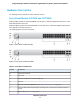
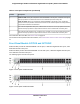


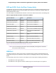
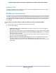

Table Of Contents
- Contents
- 1. Introduction
- 2. Hardware Overview
- 3. Installation
- Step 1: Prepare the Site
- Step 2: Protect Against Electrostatic Discharge
- Step 3: Unpack the Switch
- Step 4: Install the Switch
- Optional Step 5: Install SFP Transceiver Modules
- Step 6: Connect Devices to the Switch
- Step 7: Check the Installation
- Step 8: Apply Power and Check the LEDs
- Step 9: Manage the Switch
- 4. Applications
- 5. Troubleshooting

Table 4. LEDs on the front panel of model GC728XP and GC752XP (Continued)
DescriptionLED
Off. No link is established.
Solid green. A valid 1 Gbps link is established.
Blinking green. The port is transmitting or receiving packets at 1 Gbps.
Solid amber. A valid 10 Mbps or 100 Mbps link is established.
Blinking amber. The port is transmitting or receiving packets at 10 Mbps or 100
Mbps.
RJ-45 Left LED
Link, speed, and activity for
Ethernet ports 1 to 24 (model
GC728XP) or 48 (model
GC752XP)
Off. The port is not delivering PoE power.
Solid green. The port is delivering PoE power.
Solid amber. A PoE fault occurred.
RJ-45 right LED
Off. No SFP module link is established.
Solid green. A valid 1 Gbps link is established.
Blinking green. The SFP fiber port is transmitting or receiving packets at 1 Gbps.
Link/ACT LED
Link and activity for SFP fiber ports
25F and 26F (model GC728XP) or
49F and 50F (model GC752XP)
Off. No SFP+ module link is established.
Solid amber. A valid 1 Gbps link is established.
Blinking amber.The SFP+ fiber port is transmitting or receiving packets at 1 Gbps.
Solid green. A valid 10 Gbps link is established.
Blinking green.The SFP+ fiber port is transmitting or receiving packets at 10 Gbps.
Link/ACT LED
Link and activity for SFP+ fiber
ports 27F+ and 28F+ (model
GC728XP) or 51F+ and 52F+
(model GC752XP)
Back Panel
The back panel contains a Kensington lock for an optional security cable and an AC power connector. All
models integrate an internal power supply, require AC power, and come with a power cord.
The back panels for models GC728X, GC728XP, and GC752X are identical.
The maximum current draw varies between the models from 1A to 10A.Note
Figure 5. Back panel models GC728X, GC728XP, and GC752X
Hardware Overview
15
Insight Managed 28-Port and 52-Port Gigabit Ethernet (PoE+) Smart Cloud Switch