
GC728X-GC728XP-GC752X-GC752XP Hardware Installation Guide
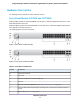
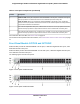


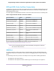
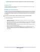

Table Of Contents
- Contents
- 1. Introduction
- 2. Hardware Overview
- 3. Installation
- Step 1: Prepare the Site
- Step 2: Protect Against Electrostatic Discharge
- Step 3: Unpack the Switch
- Step 4: Install the Switch
- Optional Step 5: Install SFP Transceiver Modules
- Step 6: Connect Devices to the Switch
- Step 7: Check the Installation
- Step 8: Apply Power and Check the LEDs
- Step 9: Manage the Switch
- 4. Applications
- 5. Troubleshooting

Table 2. Front panel components
DescriptionNumber
Cloud Connection LED1a
Power LED1b
PoE Max or Fault LED for model GC752XP only1c
Fan LED1d
Recessed multifunction Reset button (see Multifunction Reset Button on page 18)2
One micro USB console and debug port. Use this port only as directed and assisted by technical
support.
3
USB 2.0 port (see USB Port on page 17)4
Model GC752X. Forty-eight independent 10/100/1000BASE-T RJ-45 ports, numbered 1 through 48.
Each port provides one LED that functions as the combined speed and activity LED.
Model GC752XP. Forty-eight independent 10/100/1000BASE-T RJ-45 PoE+ ports, numbered 1
through 48. Each port provides a left LED that functions as the combined speed and activity LED and
a right LED that indicates the PoE status.
5
Two dedicated Gigabit SFP fiber ports, numbered 49F and 50F, that can accept optional transceiver
modules. Each port provides a single LED that functions as the combined link and activity LED.
6
Two dedicated 10G SFP fiber ports, numbered 51F+ and 52F+, that can accept optional transceiver
modules. Each port provides a single LED that functions as the combined link and activity LED.
7
For information about the LEDs, see Status LEDs on page 13.
For information about optional transceiver modules, see SFP and SFP+ Ports for Fiber Connectivity on page
17.
Status LEDs
This section describes the status LED designations of the switch.
Table 3. LEDs on the front panel of models GC728X and GC752X
DescriptionLED
Solid blue.The switch is connected to the cloud server and is set up to be managed
by the NETGEAR Insight app and Insight Cloud portal.
Off. The switch is not connected to the cloud server or is set up to be managed by
the local browser interface.
Cloud Connection LED
Solid green. The switch is powered on.
Solid amber. The switch is starting.
Off. Power is not supplied to the switch.
Power LED
Hardware Overview
13
Insight Managed 28-Port and 52-Port Gigabit Ethernet (PoE+) Smart Cloud Switch