
User Manual


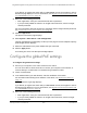


Table Of Contents
- Insight Managed 8-Port Gigabit (Hi-Power) PoE+ Smart Cloud Switch with NETGEAR FlexPoE Power
- Contents
- 1 Getting Started
- Available publications
- Switch management options and default management mode
- Manage the switch by using the local browser UI
- Access the switch
- Credentials for the local browser UI
- Register and access the switch with your NETGEAR account
- Change the management mode of the switch
- Change the language of the local browser UI
- How to configure interface settings
- Use the Device View of the local browser UI
- 2 Configure System Information
- View or define system information
- Configure the IP network settings for management access
- Configure the time settings
- Manage the denial of service settings
- Configure the DNS settings
- Configure green Ethernet settings
- Manage the Bonjour settings and view Bonjour information
- Control the LEDs
- Use the Device View
- Configure Power over Ethernet
- Configure SNMP
- Configure Link Layer Discovery Protocol
- Configure DHCP snooping
- Set up Power over Ethernet timer schedules
- 3 Configure Switching
- Configure the port settings and maximum frame size
- Configure link aggregation groups
- Configure VLANs
- Manage the basic VLAN settings
- Configure VLAN membership
- View the VLAN status
- Configure the PVID settings for an interface
- Configure a MAC-based VLAN
- Configure protocol-based VLAN groups
- Configure protocol-based VLAN Group membership
- Configure a voice VLAN
- Configure the GARP switch settings
- Configure GARP ports
- Configure Auto-VoIP
- Configure Spanning Tree Protocol
- Configure multicast
- Configure multicast VLAN registration
- View, search, and configure the MAC address table
- Configure Layer 2 loop protection
- 4 Configuring Routing
- 5 Configure Quality of Service
- 6 Manage Switch Security
- Change the local device password for the local browser UI
- Manage the RADIUS settings
- Configure TACACS+ settings
- Configure authentication lists
- Configure management access
- Control access with profiles and rules
- Configure port authentication
- Set up traffic control
- Configure access control lists
- Use the ACL Wizard to create a simple ACL
- Configure a MAC ACL
- Configure MAC ACL rules
- Configure MAC bindings
- View or delete MAC ACL bindings in the MAC binding table
- Configure a basic or extended IPv4 ACL
- Configure rules for a basic IPv4 ACL
- Configure rules for an extended IPv4 ACL
- Configure an IPv6 ACL
- Configure rules for an IPv6 ACL
- Configure IP ACL interface bindings
- View or delete IP ACL bindings in the IP ACL binding table
- Configure VLAN ACL bindings
- 7 Perform Maintenance Tasks
- 8 Manage Power over Ethernet
- 9 Monitor the Switch
- A Configuration Examples
- B Switch Default Settings and Hardware Specifications

Table 76. PoE and PoE+ device class power allocation
Device
Class
Standard Range of Power
Delivered to the
Powered Device
Minimum Output at
PoE Switch Port
(Minimum Allocated)
Maximum Output at
PoE Switch Port
(Maximum Allocated)
0 PoE and PoE+ 0.44W–12.95W 15.4W 16.2W
1 PoE and PoE+ 0.44W–3.84W 4.0W 4.2W
2 PoE and PoE+ 3.84W–6.49W 7.0W 7.4W
3 PoE and PoE+ 6.49W–12.95W 15.4W 16.2W
4 PoE+ only 12.95W–25.5W 30.0W 31.6W
Insight Managed 8-Port Gigabit (Hi-Power) PoE+ Smart Cloud Switch with NETGEAR FlexPoE Power
Manage Power over Ethernet User Manual401
Power allocation and power budget
concepts
The switch is a smart switch in that it can allocate the required power to a connected device
by using a prioritization scheme: By default, power is supplied in ascending port order (that
is, lower port numbers are served first) until the power budget is consumed and insufficient
power remains to allocate to the next device. When less than 7W of PoE power is available
on a port, the port PoE LED lights yellow, and the attached device does not receive power
from the port. However, the switch continues to send data through the port connection.
The switch is also a smart switch in that it can override the IEEE power classification of a
powered device (PD): If the PD consumes less power than required by its power
classification, the switch provides only the power that the PD consumes instead of the power
that is required by the PD’
s power classification.
If some PoE+ ports are in use and deliver power, you can calculate the available power
budget for the other PoE+ ports by subtracting the consumed (that is, delivered power) from
the total available power budget. (For information about the total available power budget, see
PoE concepts on page 400.)
An example for model GC108P:
Port 1 delivers 4.4W to a PD. If the default power adapter is installed, the available power
budget is 59.6W (64W–4.4W).
An example for model GC108PP:
A Class 4 PD is attached to Port 1, a Class 2 PD to Port 2, and another Class 4 PD to Port 3.
However
, the PDs consume less power than defined by their classes: The PD attached to
Port 1 consumes 7.3W, the PD attached to Port 2 consumes 4.7W, and the PD attached to
Port 3 consumes 8.9W. So even though the switch provides power to two Class 4 devices
and one Class 3 device, the available power budget is 105.1W (126W–7.3–4.7–8.9W).