
GC110-GC110P Hardware Installation Guide
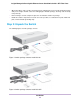
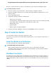
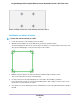
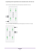
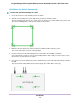
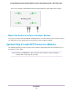
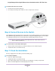
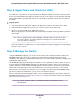
Table Of Contents
- Contents
- 1. Introduction
- 2. Hardware Overview
- 3. Applications
- 4. Installation
- Step 1: Prepare the Site
- Step 2: Protect Against Electrostatic Discharge
- Step 3: Unpack the Switch
- Step 4: Install the Switch
- Optional Step 5: Install SFP Transceiver Modules
- Step 6: Connect Devices to the Switch
- Step 7: Check the Installation
- Step 8: Apply Power and Check the LEDs
- Step 9: Manage the Switch
- 5. Troubleshooting
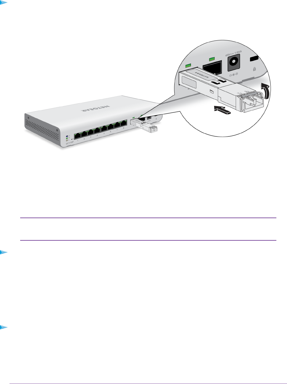
To install an SFP transceiver module:
1. Insert the transceiver into the SFP port.
2. Press firmly on the flange of the module to seat it securely into the connector.
Step 6: Connect Devices to the Switch
The following procedure describes how to connect devices to the switch’s RJ-45 ports.The switch supports
Auto Uplink technology, which allows you to attach devices using either straight-through or crossover cables.
Use a Category 5 (Cat 5), Cat 5e, or Cat 6 cable that is terminated with an RJ-45 connector.
Ethernet specifications limit the cable length between the switch and the attached
device to 328 feet (100 meters).
Note
To connect devices to the switch’s RJ-45 ports:
1. Connect a PoE or non-PoE device to an RJ-45 network port on the switch front panel.
2. Verify that all cables are installed correctly.
Step 7: Check the Installation
Before you apply power to the switch, perform the following steps.
To check the installation:
1. Inspect the equipment thoroughly.
2. Verify that all cables are installed correctly.
3. Check cable routing to make sure that cables are not damaged or creating a safety hazard.
4. Make sure that all equipment is mounted properly and securely.
Installation
28
Insight Managed 8-Port Gigabit Ethernet Smart Cloud Switch with 2 SFP Fiber Ports