
GC110-GC110P Hardware Installation Guide
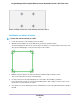
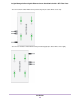
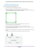
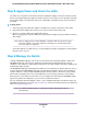
Table Of Contents
- Contents
- 1. Introduction
- 2. Hardware Overview
- 3. Applications
- 4. Installation
- Step 1: Prepare the Site
- Step 2: Protect Against Electrostatic Discharge
- Step 3: Unpack the Switch
- Step 4: Install the Switch
- Optional Step 5: Install SFP Transceiver Modules
- Step 6: Connect Devices to the Switch
- Step 7: Check the Installation
- Step 8: Apply Power and Check the LEDs
- Step 9: Manage the Switch
- 5. Troubleshooting
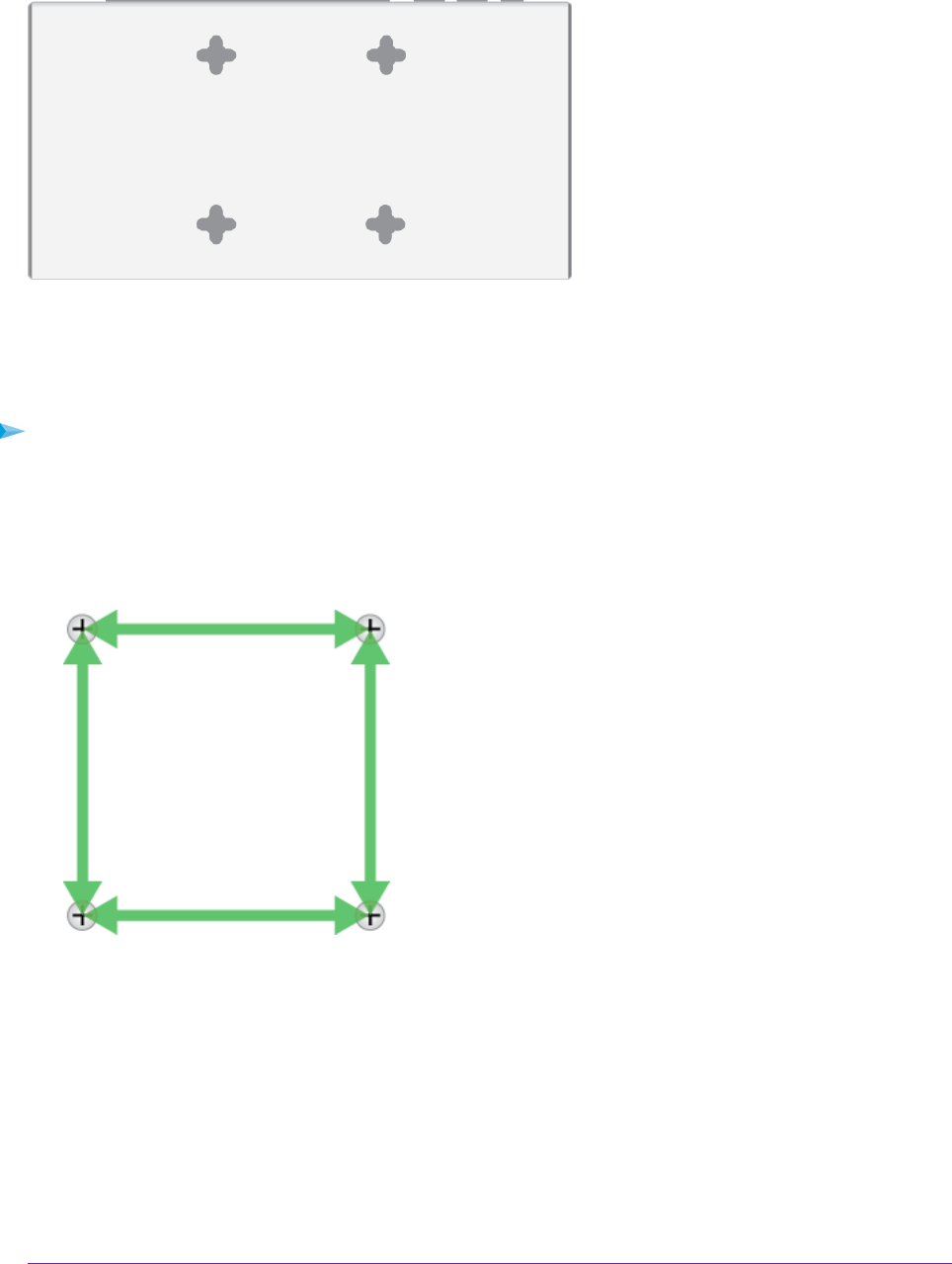
Figure 9. VESA mount holes on the bottom panel of the switch
Wall-Mount the Switch Vertically
To mount the switch vertically to a wall:
1. Locate the four holes on the bottom panel of the switch.
2. Mark the four mounting holes on the wall where you want to mount the switch.
The four mounting holes must be in a square at precise distances of 75 mm (2.953 inches) from each
other. In the following figure, each green arrow represents 75 mm.
3. Drill holes into the wall for four anchors in which you will insert M4 x L25 mm screws.
The screws and anchors are in the switch package.
4. Insert the anchors into the wall and tighten the screws with a No. 2 Phillips screwdriver.
Leave about 6 mm (¼ inch) of each screw protruding from the wall so that you can insert the screws
into the holes on the bottom of the switch.
5. Line up the holes on the bottom panel of the switch with the screws in the wall and mount the switch to
the wall.
Installation
24
Insight Managed 8-Port Gigabit Ethernet Smart Cloud Switch with 2 SFP Fiber Ports