
GC110-GC110P Hardware Installation Guide
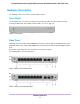
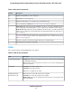
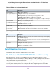
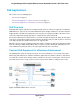
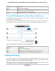
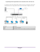
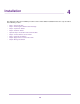
Table Of Contents
- Contents
- 1. Introduction
- 2. Hardware Overview
- 3. Applications
- 4. Installation
- Step 1: Prepare the Site
- Step 2: Protect Against Electrostatic Discharge
- Step 3: Unpack the Switch
- Step 4: Install the Switch
- Optional Step 5: Install SFP Transceiver Modules
- Step 6: Connect Devices to the Switch
- Step 7: Check the Installation
- Step 8: Apply Power and Check the LEDs
- Step 9: Manage the Switch
- 5. Troubleshooting
Hardware Description
The following sections describes the switch hardware features.
Front Panel
The front panel does not contain any components other than two LEDs: The upper LED is the Cloud
Connection LED and the lower LED is the Power LED (see LEDs on page 12).
Figure 1. Front panel
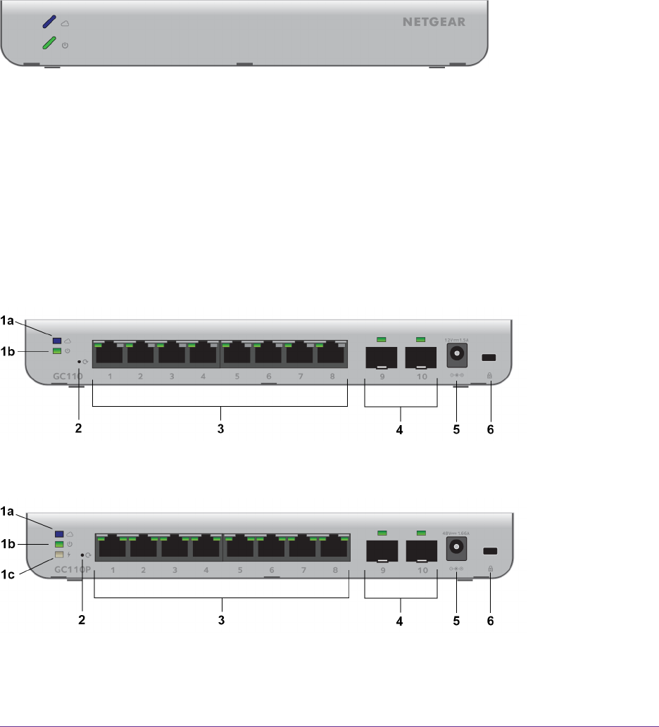
Back Panel
Model GC110 provides eight 10/100/1000BASE-T RJ-45 ports and two dedicated Gigabit SFP fiber ports.
Model GC110P provides eight 10/100/1000BASE-T RJ-45 PoE ports and two dedicated Gigabit SFP fiber
ports.
Both models require DC power and come with an external power adapter.
The following figures show the back panels.
Figure 2. Back panel model GC110
Figure 3. Back panel model GC110P
Hardware Overview
11
Insight Managed 8-Port Gigabit Ethernet Smart Cloud Switch with 2 SFP Fiber Ports